Yes. In your case, since you have the snubber across the load, if the relay closes and the capacitor of your snubber is somehow shorted, you'll put HV-AC across the snubber resistor making it go up in flames.
Should I use the fuse like on the left of the schematic and gerberview (in case the snubber fails) or like on the right (general protection of the com port)?
I did implement those components:
Fuse SGT520-8A SETsafe | SETfuse | C2997196 - LCSC Electronics
C58066 Xucheng Elec | C58066 - LCSC Electronics


The 100 ohm resistor and 0.1uF 630V polypropylene capacitor snubber is intended for use across the relay contacts not across the load
The fuse is not jut to protect against snubber failure. The failure modes are far more diverse. So the one on the left is not appropriate.
Frankly, in a case like this I'd maybe just use a fuse holder mounted in the housing of the project on the incoming AC line (either L or N). On AC projects I usually simply use a net entry part with a combined AC entry, AC mains switch and fuse holder integrated into the same part. There are many variants; e.g.:
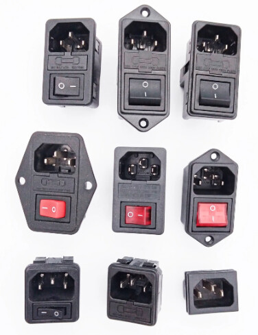
All but two of the ones pictured have a fuse holder integrated into it.
I mentioned many times that I want to have the snubber across the load, it is also state in the first post of this thread that that the leakage current when putting it across the contacts lead to wild blinking of my leds and that when dealing with LEDs, it is recommended in some guides to put it across the load.
So what capacitor will I have to buy when I want to have the capacitor across the load?
Well as you said, since the project is descined pretty much from scratch, I really got into a mood implementing everything on the pcb.
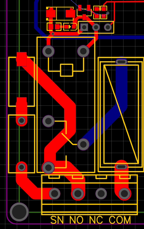
I connected it like in the right side of the schematic and rearranged the components (put the snubber on the left of the relay and the furse on the right). Also I disconnected the NC pin since it probably wont be used, but still left a 4 pin connector to have the opportunity to solder a cable on the back of the pcb.
Then feed your AC into the PCB and fork it off to each relay. That way you have a common entry point for your fuse and you don't have to fuse each relay separately. Your board will be a bit bigger to accommodate the HV-AC traces.
Since you have a net entry somewhere anyway, you can save the board space and go with one of the connectors I suggested.
I've done both depending on the project; it can work either way. Whichever you prefer.
If you absolutely must fuse every relay separately, by all means do that, just make sure that wherever you place the fuse it's actually effective.
Sorry, since you were using the 100 ohm and 0.1uf cap I though you decided to go with the snubber across the contacts. It's a tried and true solution that works in most cases.
I have no recommendations for a snubber across the load but I don't recommend using that cap for an across the mains application.
I just cloned the project and tried both versions and I think I stick with the fuses for every relay. I like the look of it ![]()
So I guess the last big problem is, what capacitor I'm goig to need. Would it help if I took one with a very high DC voltage rating such as this with 1.6kV? KP104J3C2201 KYET | C390131 - LCSC Electronics
I can't fine 100nF ones with a high AC rating

You'll find plenty that are rated for 300VAC and upwards and 100nF.
E.g. ECQ-UBAF104V2
Plenty of others, too, but this is the first I bump into.
So I can take the one rated for 300V? because earlier it was said that this was too low
AC vs DC!
My two cents:
Your entire premise of why you even need a snubber is based on the fact the some cheap relay that is known to be totally unreliable had failed. With those relays, a stuck closed failure is probably a purely mechanical issue and not because the contacts fused. Did you actually cut open the relay to determine the cause of failure?
I have an old furnace that has several 1/6 HP AC induction motors for circulation pumps, all operated by relays. So it's definitely a large inductive load, none of the relays have snubbers and they still work after 50 years. If you feel you actually need a snubber then it should go across the contacts not the load. Plus I see no need for a snubber on a string of LED lights.
I think you have gone way overboard with this snubber thing.
Put the resistor and cap across the contacts. Have one of the relays without a snubber for your LEDs and forget the fuses.
The 300V rated one I had in the schematic earlier was a AC rated one.
it was this:
If a 300V AC one does the job, I'll take the one you linked last.
After all, in the current setup (wifi MCU, relay module and snubber all connected by wires instead of one PCB), the finished bought snubber uses a 630V DC one too and it is working so far
yes, it was the first thing I did, cutting it open. I also linked a video that shows how the spark appears in a relay with much higher quality that the one in my old module:
if you google the topic of relay contacts sticking together and not opening up again, tons of people have this problem, cheap relay and expencive ones.
The welded contacts can be freed by tapping it hard. I thought it was a mechanical problem at the beginning, replacing it many times. Every time the LED one worked, the TV failed. After implementing the snubber, the TV one didnt fail a single time since. Just as described in all the guides. I noticed that you dont believe it, but having done many tests and having read so many documentations about the topic, I do believe the snubber is the way to go for my application.
this is debatable. there are many guides that show both options and discuss the advantages and disadvantages of each. for instance here: media (littelfuse.com) as shared by rsmls earlier.
just because you dont have the problem in your circuit it doesnt mean in my application it is the same.
you are right about that and since it is across the load, I can just design the PCB in a way that has all the options later. I can just not solder the resistor and capacitor and switch the LEDs without them, while soldering the components for the TV. however I always want to design the PCBs in a way I can use them in other projects later too. In the past however I sometimes had problems with the wrong components chosen which is the reason I'm researching it so much this time
I just want to make this snubber thing work, that's what this is all about.
I really dont understand why I would do that. I am using my TV maybe 2 hours a day, so the snubber would be active 22 hours more without needing it. All the time it would be leaking current. It makes so much more sense to me to have it across the load so it is only powered when the relay is actually on.
Not sure what you mean bu active but I guess it depends on your priorities, saving the relay contacts or saving a few milliwatts power.
The guy was switching a 2000W load, of course there was a spark.
He was using a 10A relay to switch a 2000W/220V = 9.1A load. Pretty stupid if you ask me.
He also put the snubber across the the relay contacts NOT the load and it worked as it should.
I just want to say that I'm ordering right now and will report back in a couple of weeks when everything arrived and has been tested.
Last change I did was remove the individual diode and capacitor and replaced it with a component that has both on it.
MRC104K300A12 Jimson | C434397 - LCSC Electronics
- It is rated for 300V AC
- The datasheet also explicitly shows that the snubber in AC circuits should be placed across the load and only in DC across the contacts
- if I should ever feel the need to place it across the contacts instead: since it is connected with a wire to the blue return cable, I could just instead wire it to the COM instead and have it across the contacts
What diode? This isn't about the snubber circuit anymore, then?
For clarity, that's not the component you linked to, right? That's just a capacitor.
I'm sorry, I meant the resistor, not diode.
The component I linked has both in it: a 120 Ohms resistor and a capacitor with 0.1uF 300V AC
Hmmm...I see; well, the datasheet is kind of unclear about it. I'll take your word for it.
Just to conclude
- I finished the PCB and did not soldered the snubber at the beginning
- Even with the high quality and more expencive finder relays, it did not even take a week until they got stuck too and the TV and Soundsystem did not turn off anymore
- A very bright arc was visible through the transparent relay
- I then soldered the snubber and since then it works perfectly fine!
- there is still a visible arc but it is MUCH dimmer, not so bright and strong