I'm trying to multiplex the antenna output of the RFID board I have to multiple antennas so I can determine which one is being read. Of course I can have more readers but I'm trying to save money.
I can get the multiplexer working with just normal voltage applied to the input with the LEDs turning on at their designated slots. Currently I have it changing the output every 100ms.
When I try to connect the antenna from the RFID board the LEDs (I'm only using them to test but not in the final design) they no longer follow the sequence but twinkle. They mostly stay on with a slight dimming every now and then but not in the correct sequence.
I can get multiple external antenna working fine without the multiplexer but of course I can't then tell them apart.
I'm quite new to antenna design so have no idea why or what is happening here.
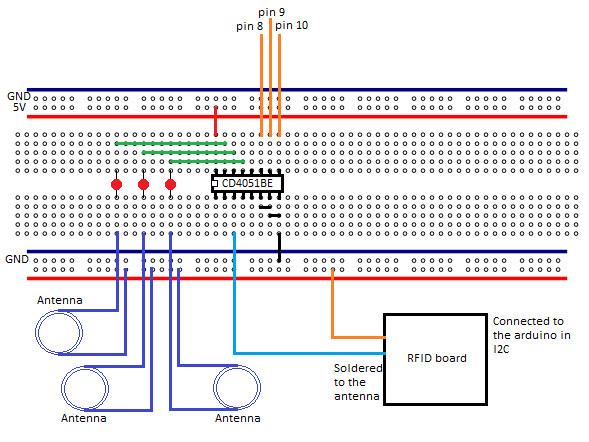
Attached is a sketch of my wiring and a photo of how i connected to the antenna on the RFID board.
Thanks for posting the pics.
It's like the 4051 stops working correctly and stops switching to the different outputs when the antenna is connected. I have no idea why as i though each output is isolated?
Are there any alternatives that could work instead? I'm probably going to want around 8 of these and at $10 each on ebay I'm not sure I want that many.
Im trying to have it cycle through the external antenna so when something is read on one I will know what antenna was active at that time so I know where the card was read.
Yeah sorry fairly new to this and the best I can do.
Thank you for your help. Do you know what a better alternative would be? Reed relays? Only thing would be that it will likely require more pins on the arduino to control all that I need. Or I guess I could use the 4051 to control relays?
It might just be best to buy more RFID receivers and slave them to the arduino.
Relays might work I suppose. I'm not an expert on rf antennas, but I know they have to be designed very carefully. Length is absolutely critical, and putting extra components between the antenna and the receiver circuit can badly affect the sensitivity. The other problem with relays is that you will be constantly switching them, causing them to wear out quickly.
I think your best chance of success is with multiple receivers. I think they are i2c devices, which means they all have to have a different address on the bus. If there is no way to achieve that, you may need an i2c multiplexer.
Looking closer at the picture of the receiver circuit, it looks like it also has an SPI interface with a Chip Select (CS) pin, so that could be an option.
I have a 13.56MHz RFID Reader, by doing some more research it looks like it won't work with the 4051.
I have been looking at some RF switches and in particular SW-289 GaAs DPDT Switch on ebay. Attached is a datasheet. It says up to 2GHz, which I presume would allow it to run correctly at 13.56MHz? Do you think if no voltage is applied to A or B it would have no output? Or whatever state it was in last?
If they are suitable then I can use the 4051 as the controller of the SW-289's.
The antenna is three loops of 0.12mm 8 strand wire at 60mm diameter. The voltage increases to 3.6v from 2.2v and is grounded to the arduino.
This antenna work as well as the one built into the board based on distance.
All I'm trying to achieve is to be able to switch between multiple antenna loops.
Where did you finish up with this project. Hopefully have something working. I have something similar in mind using Arduino etc. Read tag (into MS Excel) and record location (say 1 of 20).