so i want A circuit that can go between 5v and 3.3 v
The 5v is the direct usb voltage , and the 3.3 volts is with an ams regulator.
You pick between them with a jumper .
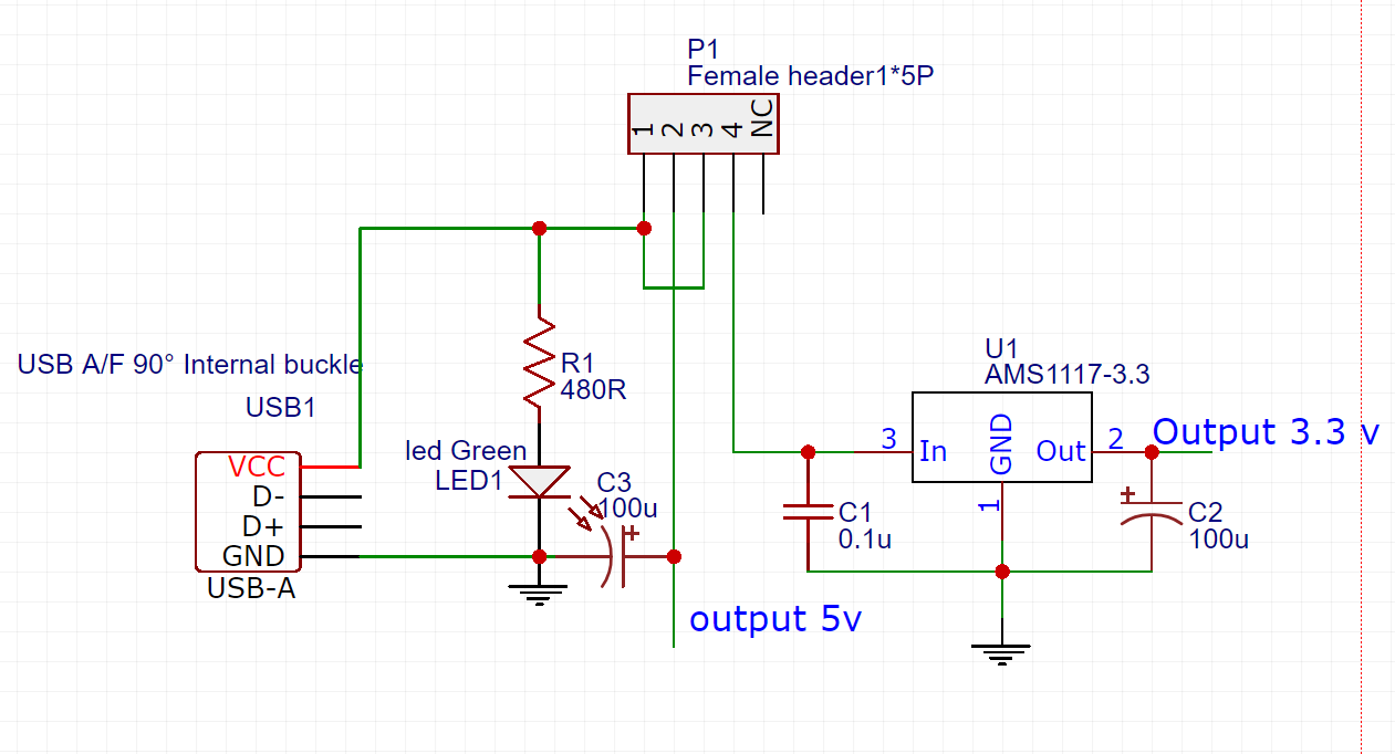
this is my circuit.
Do i have some big mistake ?
i'm not sure about the smoothing capacitors .
What does the data sheet say about the type and size of the output capacitor?
groundFungus:
What does the data sheet say about the type and size of the output capacitor?
it says to add 22uF solid tantalum , but i don't have one of those .
I saw some youtube videos using the same regulator and they used a 100uF on the ooutput .
Will it make a difference ?
DAoliHVAR:
it says to add 22uF solid tantalum , but i don't have one of those .
I saw some youtube videos using the same regulator and they used a 100uF on the ooutput .
As the datasheet says, larger values can be used to "to further improve stability and transient response of these devices."
Specifically calling out "solid tantalum" is just to say that you want to use something that is stable with voltage and temperature, which a ceramic is not. Most designers putting in a small surface mount LDO wouldn't put an aluminum electrolytic 3-times its physical next to it.
I would not put a 100nF, by itself, on the input. The input capacitor is a decoupling capacitor, it is there to decouple the regulator from the rest of the circuit. Something like a 10-100uF is probably more suitable there.
OP's circuit:
I'm used to seeing 100 nF ceramic + 10-100 uF tantalum or electrolytic on both sides of the regulator. Indeed check the data sheet.
Normally a tantalum cap can be replaced by an electrolytic cap, and later values are normally no problem, but don't make them more than 10x as big. The initial charge peak may become an issue.