I'm new to Arduino and am using the R4 to power some low voltage breadboard stuff. I picked up an R3 at the same time. It seems like the 5V out is consistently measuring about .3V less on the R4. Do I have a faulty board or is there a reason for this?
How are you powering the boards?
I've used various USB ports. The last one was off of a USB dock which measured 4.7 on the R4 and 5.06 on the R3. The USB is for convenience, I have my laptop with me at school and I think got something around 4.7 again.
Are you measuring both output voltages with or without a load?
Both are measured while they are USB powered and with a multimeter attached to jumpers in the GND and 5V pins.
Nothing is "perfect" in the real-analog world and under-or-over by 1/4V or so isn't a problem for 5V logic.
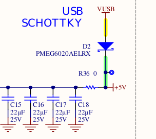
I haven't looked at the R4 schematics but on the R3, 5V is not directly-connected to 5V USB power. I think there's a diode and/or MOSFET and it wouldn't be unusual to get some voltage drop.
The 5V from the USB connector is going through a diode to the 5V pin.
2 Likes
So I'll never get to 5V without something else boosting it in between? I don't see it being an issue, I just wanted to make sure what I have is standard. Thanks.
It is standard.
If you want 5.0V at the 5V pin, then you have to apply a voltage of 6 to 24V to the the DC barrel jack or the VIN pin.
You have several tolerances to keep in mind. What is the accuracy of the meter? What is the tolerance of the regulator? What is the dropout voltage for the regulator? What is the input voltage? All of these can stack up and give you a error of 0.3 volts without anything wrong. What is the voltage range of the processor, if you are in that range it should be OK.
The main purpose was to figure out why R3 read 5V but R4 did not. As I mentioned I'm new to Arduino (and DIY electronics in general) and had no idea there was a published schematic I could read. The diode makes sense. Input voltage and meter accuracy have no play here because all I want is the measurement relative to the R3. Again new to it. Just wanted to make sure I had a functioning unit.
The 5V pin should measure at least 4.7V and this is due to the voltage drop accross the D2 diode.
2 Likes
I have noticed that if one is connecting another 5V Arduino board e.g. a Leonardo to act as a D0-D1 Serial to USB connection, the logic high levels are interacting.
So would be good to add say 470R series resistors between the R4 pins and the Leonardo/Other 5V board's pins.
Renesas info here:
https://www.renesas.com/us/en/document/apn/ra-family-mcu-injection-current-prevent-damage-mcu-application-notes
My 5V pin on R4 Minima is reading 3.3V. I've checked on two boards.
I'm powering via the USB cable. From reading this thread I would expect it to be around 4.7v.
What else should I check ?
Hmm, I've just powered it up from a 12v supply and it is now reading 4.99v. End of the problem ![]()