Ok thank you Mark! I would gladly wait for your reply.
One quick sidenote, I used a USB to RS485 and used the software that the sensor uses in testing all the parameters that is in the sensor and it displays all of the values so I assume that my sensor is not defective.

In this photo, the Phosphorus and Potassium don't have any values but when they are tested independently, they returned some readings.
I also compared the array that is sent by the software and it is the same with all of the arrays in my arduino code. Do you think that the problem is between the sensor and the max485 module?or the communication of arduino to the max485? Thank you so much for your help Mark.
1 Like
That screenshot is a help. It confirms that your device address is 1. Whatever baud rate that PC software uses is also the baud rate you need too.
The PC software appears to be getting your sensor to respond as follows:
Register    Description
  0006      pH (x10)
  0012      Soil moisture (x10)
  0013      Soil temperature (x10)
  0015      Electrical conductivity (x10)
  001E      Nitrogen (x1)
  001F      Potassium (x1)
  0020      Sodium (x1)
Off the top of my head, I'd say that the pH isn't 0.5 and that the temperature isn't 155.9degC (or degF)!
The PC software is querying register 0x0013 for temperature BUT your document says that it should be register 0x0001. Clearly the PC software (which I think is one of the PC apps that I've seen provided by other forum members for their particular NPK sensor) isn't configured for your particular sensor.
What's interesting is that the document doesn't show any registers from address 0x0009 up to address 0x0021, yet your particular sensor is responding with some values.
We now know that the sensor is doing something - i.e. responding to Modbus messages over RS485, and that its address is 1. Does the PC app show a baud rate?
Yes, you can set the baudrate in the software. The sensor only returns the readings when the baudrate is at 4800. The screenshot of the reading is when the sensor is not inserted in the soil thus the 0.5pH reading. But I also tried to place it in the soil but both the Phosphorus and Potassium values were still zero
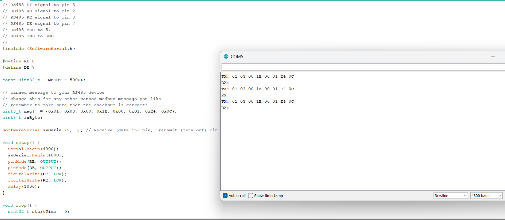
Re your post #8, if you are using the code that I provided in that post, the a quick baud rate change should work:
// This attempt uses the SoftwareSerial & raw Modbus packets.
//
// RS485 module wired up as:
// RS485 DI signal to pin 3
// RS485 RO signal to pin 2
// RS485 RE signal to pin 8
// RS485 DE signal to pin 7
// RS485 VCC to 5V
// RS485 GND to GND
//
#include <SoftwareSerial.h>

#define RE 8
#define DE 7

const uint32_t TIMEOUT = 500UL;

// canned message to your RS485 device
// change this for any other canned modbus message you like
// remember to make sure that the checksum is correct!
uint8_t msg[] = {0x01, 0x03, 0x00, 0x1E, 0x00, 0x01, 0xE4, 0x0C};
uint8_t rxByte;

SoftwareSerial swSerial(2, 3); // Receive (data in) pin, Transmit (data out) pin

void setup() {
  Serial.begin(9600);
  swSerial.begin(4800);
  pinMode(RE, OUTPUT);
  pinMode(DE, OUTPUT);
  digitalWrite(DE, LOW);
  digitalWrite(RE, LOW);
  delay(1000);
}

void loop() {
  uint32_t startTime = 0;

  Serial.print("TX: ");
  printHexMessage( msg, sizeof(msg) );

  // send the command
  digitalWrite(DE, HIGH);
  digitalWrite(RE, HIGH);
  delay( 10 );
  swSerial.write( msg, sizeof(msg) );
  swSerial.flush();
  digitalWrite(DE, LOW);
  digitalWrite(RE, LOW);

  Serial.print("RX: ");

  // read any data received and print it out
  startTime = millis();
  while ( millis() - startTime <= TIMEOUT ) {
    if (swSerial.available()) {
      printHexByte(swSerial.read());
    }
  }
  Serial.println();
  delay(2000);
}

void printHexMessage( uint8_t values[], uint8_t sz ) {
  for (uint8_t i = 0; i < sz; i++) {
    printHexByte( values[i] );
  }
  Serial.println();
}

void printHexByte(byte b)
{
  Serial.print((b >> 4) & 0xF, HEX);
  Serial.print(b & 0xF, HEX);
  Serial.print(' ');
}
Then you should get a reply if wired as per your image in post #1. Make sure that you have a GND between the Arduino, MAX485 module and the sensor.
Check that you have your A & B the right way round - try swapping them over just in case.
EDIT: I'm beginning to suspect that the datasheet you have been given does not match the sensor you have.
I tried the program that you wrote again and changed the baudrate as you mentioned and unfortunately, the serial output is still the same. I also tried swapping the A & B wires but it's still the same.
I also tried changing the two baudrates but it's still gives the same output.
Don't worry about the baud rate of the Serial.begin function call - that's to do with communicating with the IDE.
Ok, now it's time for some detective work. When you used your PC app, you had a USB-RS485 dongle. We can use that same dongle to see what's happening with your Arduino setup.
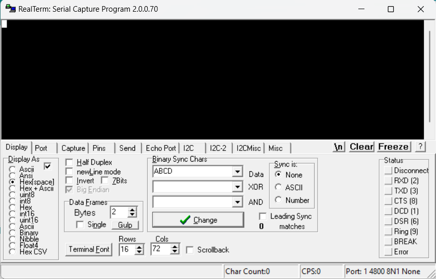
If you don't have it already, download RealTerm - it's free. There's a nice writeup on the Sparkfun website about it here.
With your sensor, your MAX485 board and your Arduino all connected up, plug your USB dongle into your PC and connect its A & B wires to the A & B wires of the MAX485 board - and GND as well if the dongle has one.
Open up RealTerm, set the Com port for the USB-RS485 dongle and the baud rate to 4800. See the Sparkfun writeup for details on how to do this.
Also look at the section "Adjusting the Display" and set it to Hex [space].
With your Arduino code running, you should see data being displayed by RealTerm.
I have done everything that you said and connected my USB-RS485 to the sensor, arduino, and max485. After setting up the settings in the said website which can be seen in this screenshot.
Will there be an automatic output in the Realterm software or I need to manually input the values? because as you can see, the arduino code is already running and nothing is happening to the Realterm Software.
Ok. If you see nothing in the Realterm window, the that suggests that there is a problem with the transmission of the message from the Arduino.
There are only 4 signals from the Arduino to the MAX485 module. RE & DE control the direction of flow of the data (i.e. transmit and receive). In this case, it doesn't matter if you have RE & DE mixed up.
Check that you have RO & DI wired correctly as that does matter.
Note that we can't do a simple loopback test as SoftwareSerial cannot transmit and receive at the same time.
If your wiring is correct, then we may need to switch to a different software serial library that can transmit and receive at the same time in order to figure out where the problem may be.
What software serial library should we try next?
I would head straight for AltSoftSerial. This a modified, but untested, version of my previous test code that uses AltSoftSerial:
// This attempt uses the AltSoftSerial library & raw Modbus packets.
//
// RS485 module wired up as:
// RS485 DI signal to pin 9   <- It has to be this pin
// RS485 RO signal to pin 8   <- It has to be this pin
// RS485 RE signal to pin 6   <- I had to move RE to another pin
// RS485 DE signal to pin 7
// RS485 VCC to 5V
// RS485 GND to GND
//
#include <AltSoftSerial.h>

#define RE 6
#define DE 7

const uint32_t TIMEOUT = 500UL;

// canned message to your RS485 device
// change this for any other canned modbus message you like
// remember to make sure that the checksum is correct!
uint8_t msg[] = {0x01, 0x03, 0x00, 0x1E, 0x00, 0x01, 0xE4, 0x0C};
uint8_t rxByte;

AltSoftSerial swSerial;

void setup() {
  Serial.begin(9600);
  swSerial.begin(4800);
  pinMode(RE, OUTPUT);
  pinMode(DE, OUTPUT);
  digitalWrite(DE, LOW);
  digitalWrite(RE, LOW);
  delay(1000);
}

void loop() {
  uint32_t startTime = 0;

  Serial.print("TX: ");
  printHexMessage( msg, sizeof(msg) );

  // send the command
  digitalWrite(DE, HIGH);
  digitalWrite(RE, HIGH);
  delay( 10 );
  swSerial.write( msg, sizeof(msg) );
  swSerial.flush();
  digitalWrite(DE, LOW);
  digitalWrite(RE, LOW);

  Serial.print("RX: ");

  // read any data received and print it out
  startTime = millis();
  while ( millis() - startTime <= TIMEOUT ) {
    if (swSerial.available()) {
      printHexByte(swSerial.read());
    }
  }
  Serial.println();
  delay(2000);
}

void printHexMessage( uint8_t values[], uint8_t sz ) {
  for (uint8_t i = 0; i < sz; i++) {
    printHexByte( values[i] );
  }
  Serial.println();
}

void printHexByte(byte b)
{
  Serial.print((b >> 4) & 0xF, HEX);
  Serial.print(b & 0xF, HEX);
  Serial.print(' ');
}
With AltSoftSerial, you have to use pins 8 & 9 - you can't choose like you could with SoftwareSerial. I had to move RE to pin 6 as pin 8 is needed by AltSoftSerial.
See if you get anything displayed at all in Realterm.
If you get nothing displayed, then we can go back to real basics and join pin 8 to pin 9 on the Arduino. The Arduino will essentially be talking to itself and the IDE should show an RX message exactly the same as the TX message.
There's still nothing on the Realterm software. On the other hand there is now a single reply of 00 in the RX which you can see in this screenshot:
What do you mean by joining pin 8 to pin 9 in the arduino?
As it stands, you should have pins 8 and 9 on your Arduino connected to the RO & DI pins on the MAX485 board - as detailed in my comments on the latest test code.
Disconnect the 2 wires from pins 8 and 9, and then use a wire link to connect pin 8 to pin 9. The Arduino should now be talking to itself - like a standard loopback test mode.
I've successfully connected pins 8 and 9 and the arduino is talking to itself because it returned the same value as the TX as seen in this screenshot:
What should we do next?
Right. Now we know that the Arduino can transmit data and receive data.
Remove the wire between pins 8 & 9 and connect pins 8 & 9 back onto the MAX485 board.
Now modify the code from this:
  // send the command
  digitalWrite(DE, HIGH);
  digitalWrite(RE, HIGH);
  delay( 10 );
  swSerial.write( msg, sizeof(msg) );
  swSerial.flush();
  digitalWrite(DE, LOW);
  digitalWrite(RE, LOW);
to this:
  // send the command
  digitalWrite(DE, HIGH);
  digitalWrite(RE, LOW);      // <- change this line
  delay( 10 );
  swSerial.write( msg, sizeof(msg) );
  swSerial.flush();
  delay(100);                 // <- and add this line
  digitalWrite(DE, LOW);
  digitalWrite(RE, LOW);
What this should do is put the RS485 module into loopback mode so that it hears its own transmission. This should be picked up by the Arduino and displayed just like the previous test.
Note that you should disconnect the NPK sensor - but leave the USB dongle connected to A & B and Realterm running.
Hopefully you should also see the message appear in Realterm as well.
Unfortunately it doesn't send the TX back to the RX. I already disconnected the sensor and attached the A & B Pins of the dongle to the MAX485. This is the result from your updated code:
FYI also, this is the USB-RS485 that I am using
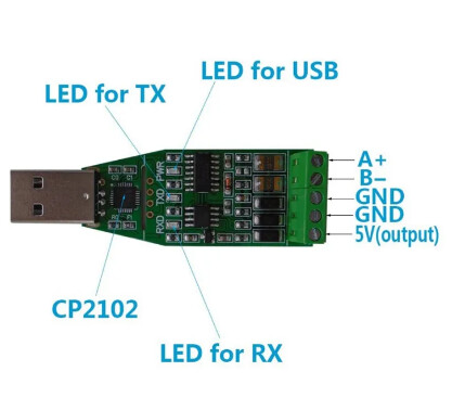
I've connected the A & B Pins to the A & B of the MAX485 and connected one of the GND pins to the common ground of the components.
This is beginning to sound like the MAX485 board isn't working.
We know that the Arduino can talk to itself. When we introduce the MAX485 board, it doesn't appear to want to transmit any data. That would explain why you don't see anything in Realterm and why your sensor doesn't respond.
I have a similar USB-RS485 dongle although mine is in a translucent case.
We know that your USB-RS485 dongle is working as your PC program can talk to the sensor. It's a useful tool to have especially when trying to figure out problems like this.
Do you have a spare MAX485 board you can try?
Does your RS485 module look like this:
Yes, my MAX485 is exactly that. Unfortunately I don't have a spare MAX485 as of the moment. What I have is this one:
Can I use this one instead? It's called RS485 to TTL Converter Module
Yes. You can use that one. It doesn't have the RE & DE pins as it's an auto switching board. I don't think we can try the loopback tests with a board like that.
However, you can still send out the messages and see if Realterm can pick them up.
I seem to recall that TXD = RO and RXD = DI.
I tried using it and I think that I'm doing something wrong. I connected the TXD to pin 8 and the RXD to pin 9, pins A & B to the USB-RS485, and GND and VCC pins but it still doesn't return the RX value as seen in this screenshot:
Should I also change something to the testing code? Here is my current testing code:
// This attempt uses the AltSoftSerial library & raw Modbus packets.
//
// RS485 module wired up as:
// RS485 DI signal to pin 9   <- It has to be this pin
// RS485 RO signal to pin 8   <- It has to be this pin
// RS485 RE signal to pin 6   <- I had to move RE to another pin
// RS485 DE signal to pin 7
// RS485 VCC to 5V
// RS485 GND to GND
//
#include <AltSoftSerial.h>

#define RE 6
#define DE 7

const uint32_t TIMEOUT = 500UL;

// canned message to your RS485 device
// change this for any other canned modbus message you like
// remember to make sure that the checksum is correct!
uint8_t msg[] = {0x01, 0x03, 0x00, 0x1E, 0x00, 0x01, 0xE4, 0x0C};
uint8_t rxByte;

AltSoftSerial swSerial;

void setup() {
  Serial.begin(9600);
  swSerial.begin(4800);
  pinMode(RE, OUTPUT);
  pinMode(DE, OUTPUT);
  digitalWrite(DE, LOW);
  digitalWrite(RE, LOW);
  delay(1000);
}

void loop() {
  uint32_t startTime = 0;

  Serial.print("TX: ");
  printHexMessage( msg, sizeof(msg) );

  // send the command
  digitalWrite(DE, HIGH);
  digitalWrite(RE, LOW);      // <- change this line
  delay( 10 );
  swSerial.write( msg, sizeof(msg) );
  swSerial.flush();
  delay(100);                 // <- and add this line
  digitalWrite(DE, LOW);
  digitalWrite(RE, LOW);

  Serial.print("RX: ");

  // read any data received and print it out
  startTime = millis();
  while ( millis() - startTime <= TIMEOUT ) {
    if (swSerial.available()) {
      printHexByte(swSerial.read());
    }
  }
  Serial.println();
  delay(2000);
}

void printHexMessage( uint8_t values[], uint8_t sz ) {
  for (uint8_t i = 0; i < sz; i++) {
    printHexByte( values[i] );
  }
  Serial.println();
}

void printHexByte(byte b)
{
  Serial.print((b >> 4) & 0xF, HEX);
  Serial.print(b & 0xF, HEX);
  Serial.print(' ');
}
That code should result in you seeing something in Realterm. You shouldn't see an RX message in the Arduino IDE as you don't have the sensor connected (do you?), and I don't think you can do an RS485 loopback test with that module.
All the RE & DE pin manipulation code can stay - there's nowhere to connect those pins to on your auto switching board.
The main test is whether you see anything in Realterm that would indicate that the Arduino & RS485 module are working together to transmit the test message.