Yes I have the sensor disconnected. But there is still nothing on the Realterm software it's still empty ![]()
Just as a sanity check for myself and to make sure that the MAX485 loopback code works, I've just wired up an UNO and one of those RS485 modules and run the loopback code. I get back the message I'm sending:
TX: 01 03 00 1E 00 01 E4 0C
RX: 01 03 00 1E 00 01 E4 0C
TX: 01 03 00 1E 00 01 E4 0C
RX: 01 03 00 1E 00 01 E4 0C
Hmm.
Ok, can you upload a photo (or several) that show how you have the Arduino, RS485 module and USB dongle connected?


From what I can see, that looks ok. One thing I would try - just in case - those 4 wires at the top that are the GND signal - put them all next to each other if you can in one of the sets of 5 holes - either along the "power rail" or in one of the vertical rows on the breadboard.
This is just in case there is a break in that power rail at the top. I think I read somewhere in one discussion a while back that it was an issue with a particular breadboard.
You might find that the GND on your RS485 module at the bottom in your picture is connected to the GND next to the A & B signals. If that's the case, you can take the GND on your Nano directly to the GND at the bottom of your RS485 module. And take the GND next to A & B and run it directly to the USB-RS485 module.
Another thing you can try just to see if anything is alive, is type something in on Realterm and see if the Nano shows anything on the RX line.
EDIT: Also, is there any activity on the RX & TX LEDs?
Getting late here so I may not be able to reply again for a while.
Alright thanks for the tip, I already changed the GND connections. I can't type on the Realterm but everytime I press a key from my keyboard the TXD in the status lights up in yellow.

To answer your question yes there is an activity in the RX and TX LEDs. The TX LED of the Arduino lights up in sync with the RXD LED of the RS485 module.
Thank you for your help today Mark! I will also get back to you when I'm able to buy another MAX485 module, that's probably on Wednesday here in the Philippines.
That sounds like the Arduino is sending data and the RS485 module is detecting it.
Okay I’ll try to connect the sensor to the RS485 again tomorrow. Hopefully it works.
Ignore that. I'm talking rubbish. The TX LED on the Nano flashes when it sends a character out the hardware serial port to the IDE.
The LEDs on the RS485 module and the USB dongle are the best indicators of activity.
Hello. I tried the Realterm again, this time I selected the port which is where the arduino nano is connected and I got this response from the Realterm Software.
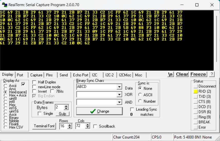
The connections are the RS485 module and the USB dongle to the arduino just like last night. But when I switch to the port where the USB dongle is connected, nothing displays in the Realterm.
Btw I'm running the code that I mentioned in post #39
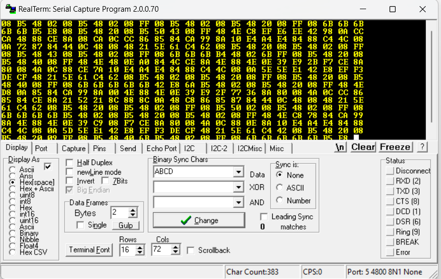
EDIT: I tried to run Realterm together with the sensor and I run the code which measures all the parameters mentioned in post #11 and here is the response from Realterm. Again I choose the port where the arduino nano is connected which is COM 5.
But the values returned in the Serial Monitor of the Arduino IDE is still the same

I also tried the suspected broken MAX485 module together with the sensor and Arduino. After running the code. I checked the Realterm software and choose port 5 which is where the Arduino is connected then I also got a response in Realterm.
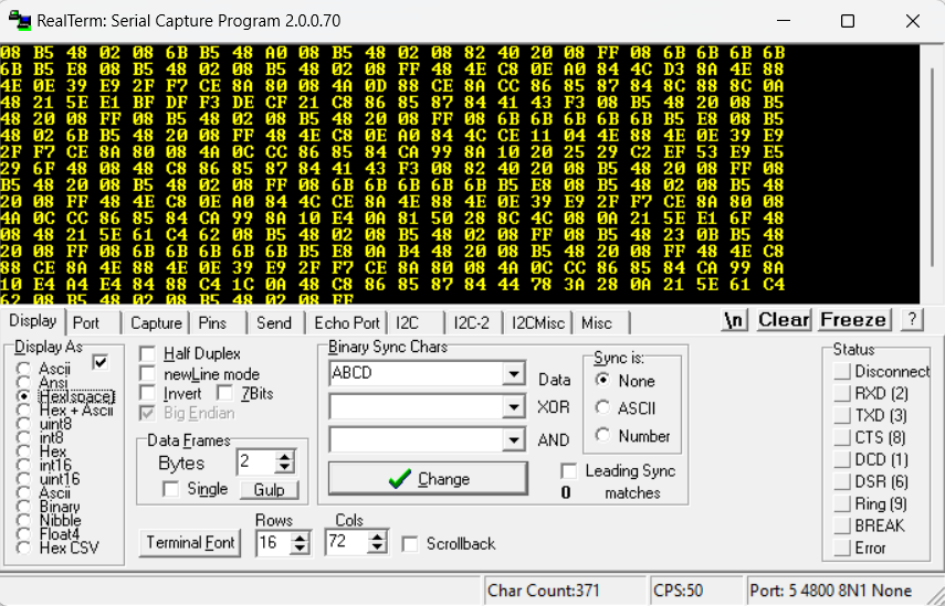
And after checking the Serial Monitor, the outputs are still the same as the response in post #50
That would be the sort of data I would expect to see. You are seeing Realterm trying to interpret the serial output that you saw on the IDE serial monitor. Realterm is showing it like that because the software was configured for 9600 baud on the hardware serial port and Realterm is set for 4800 baud.
It would be damn unlucky if 2 different RS485 interface boards were both faulty.
At this stage, I would probably be using the auto switching board - mainly because it has LEDs to show when it believes data is being transmitted and received, and because of its auto switching nature, it reduces the number of wires that can be connected incorrectly by 2 - no need for RE & DE signals.
With your Nano running the sketch, you should see the TX LED flash briefly each time the Nano sends out a message. I believe that your USB RS485 module may also have an LED for RX that should flash in sync with the TX LED. If that happens, then your Nano is sending data and the USB RS485 module is detecting it. Realterm should be able to show you what that data is.
One quick question though, what pins should I connect the RXD and TXD pins of the auto switching board to my arduino nano?
Are you saying that I should change the Realterm's baudrate to 9600?
Another side note. Do you think that the processor is one of the reasons to why I'm not able to get the message that I am sending because I am using the Atmega328P (Old Bootloader) because when I'm using the latest Atmega328P processor there's always an error which says that it "cant't set com-state" for the port. The wrap around that I did is that I downgraded my USB port driver an used the "Old Bootloader" and that is when I can upload my sketches to my nano.

I ran the sketch again using the auto switching module but this time I changed the baudrate of the Realterm to 9600 and here are the results that I got.
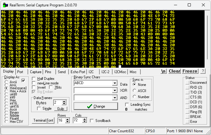
That looks about right. Those are the ASCII codes for the characters that the IDE would normally show you. You can see the real text by selecting display as ASCII.
There has been discussion recently in the forum regarding this. I think one of the Arduino team mentioned a problem with a software update (possibly Microsoft). Reinstalling the USB driver was one fix - if I recall correctly.

I tried that already but it doesn't work for me. The thing that works for me is that
That's correct. The IDE and Realterm are both looking at the hardware serial port on the Nano.
Re connecting the auto switching RS485 module, start with 5v, GND and the Nano software serial port TX wire. With nothing else connected, the RS485 module TX LED should flash with each transmission.

Interesting. Ok. So if you run the sketch that we had back in post #30 (the one that used AltSoftSerial), and connected pin 9 of your Nano to the TXD pin of the auto switching unit, does the TX LED still flash on the auto switching unit?