I tried also with "i2c_scanner" but response is : "No I2C devices found".. what could be the problem? ![]()
Hmmm... I was wondering why your code is setting pin 3 to an output and low. But now I'm looking at your schematic (don't know if it's the latest) and I see that pin 3 is hooked up to the reset lines of all of the chips.
Besides the SCL and SDA pins you are using, these I2C signals are also on pins 2 and 3. Once you initialize the wire library, I'm sure it's re-setting pin 3 to be the SCL signal, overriding your settings.
However, that means that the SCL line is being fed to the reset pins of your chips. Every I2C clock cycle is resetting those chips! I don't know why none of us saw this before now. :o
For a quick test, gently bend the pin 3 shield pin out of the way so it isn't making contact with the Yun, and use a jumper to temporarily hold that unconnected pin at 5V, and see if it works.
If that makes it work, then you will need to cut the trace going to shield pin 3, and jump it somewhere else, like to pin 4. (A hobby razor knife and a very thin piece of wire will come in handy here. I use solid core wire-wrap wire for such jumpers.)
Another issue is that you are setting pin 3 low. The reset pin is an active low signal, so by holding the line low you would be holding the chip in reset. I say "would be" because the pin will be redefined as I2C by Wire.begin(). But it's something to keep in mind when you move it to another pin: initially set the pin LOW to reset the chip, but then set it HIGH and keep it there to be able to use the chip.
YOU ARE A GENIUS! ![]()
Just move outside pin 3 and connected to 5v and now:
ADDR SEL 0000:
Scanning...
I2C device found at address 0x20 !
I2C device found at address 0x21 !
I2C device found at address 0x23 !
done
ADDR SEL 0001:
Scanning...
I2C device found at address 0x24 !
I2C device found at address 0x25 !
I2C device found at address 0x27 !
done
YEAHHH ![]()
uhm. but where is third chip? ![]()
Double check all of the connections to that chip. Are the address lines set right? Are there any shorts between pins? Are there any cold solder joints that aren't really making contact? Is the chip in backwards? Is there a lot of flux or other gunk around the pins that needs to be cleaned out?
I not used pin 4 because ethernet shield use it for SD.
I tried to set:
Wire.begin();
pinMode(3, OUTPUT);
digitalWrite(3, HIGH);
But it doesn't work.. so i should only to cut pin 3 and no use reset? ![]()
I'll check chip 3 connections!
I'll also use hot air gun for solder SMD chips, maybe i warmed too much the chip 3 (we was testing time and themp for best soldering.. )
Ok found it, one of address pin was not right soldered! ![]()
How can i solve pin 3 issue without redraw pcb? ![]()
leen15:
I tried to set:Wire.begin();
pinMode(3, OUTPUT);
digitalWrite(3, HIGH);But it doesn't work.. so i should only to cut pin 3 and no use reset?
You're right, that won't work. Wire.begin() is initializing the pin to be part of the I2C hardware interface. Then, you are re-initializing the pin to always be high, taking the pin function away from I2C. Then, when you try to perform an I2C operation, SDA is being sent, but SCL is blocked because now the signal is always high.
You MUST cut the connection to pin 3. There is no software workaround. Once cut, either tie the pin always high and don't have any reset function, or better yet tie it to the shield reset pin so the chips are reset whenever the 32U4 processor is reset, or best option is tie it to another shield pin and use that as the reset signal.
leen15:
How can i solve pin 3 issue without redraw pcb?
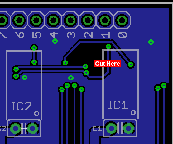
Cut the trace leading to pin 3. Do it on the bottom of the board where it's less visible (see attached.) Using a hobby razor knife carefully cut a gap in the trace. Then, solder a fine jumper wire from one of the reset pins at the chip (or one of the vias in the chain if they don't have soldermask) and connect it to +5v, the shield reset pin, or another shield I/O pin. If possible to solder onto one of the vias, I would put the jumper on the bottom of the board, going from the desired shield I/O pin to the nearest via on that trace.
An example of a cut and jumped trace:

Note how the trace was cut through just above the right end of the black wire, and then a fine wire was soldered in to make the correct connection. Note how the wire is glued down to the board - this is a very good idea. Either cyanoacrilate super glue can be used, or blobs of hot melt glue.
This is not an unusual situation, it's quite common for there to be several cuts and jumps on a new board design. If this is the only issue that crops up, you're doing great!
Having a look here: Arduino Playground - Shield Pin Usage
Pin 9 could be a good candidate for replace pin 3, right? I would avoid to make a shield that is incompatible with ethernet shield and gsm shield, that i think they are the most used.
Is it a bad idea if i cut pin out of pin 3 and attach it to pin 9?
I think there is too way to arrive at reset pin for make it with a bottom wire..
i usually i dont like external wire on pcb but it seem the only solution ![]()
leen15:
Is it a bad idea if i cut pin out of pin 3 and attach it to pin 9?
I'm not sure what you're saying here.
ShapeShifter:
I'm not sure what you're saying here.
Sorry for my bad english ![]()
I mean cut pin 3 and solder a wire between pin 3 and pin 9 on bottom of shield. ![]()
You could do that. But it would be a cleaner mod if you could solder a jumper from pin 9 to the nearest via on that line. If you can, then cut the trace where I indicated. It all comes down to whether the vias have solder mask over them. If not, that's a cleaner way to go, as it leaves the circuit in place through pin 3 in case you add a shield that uses those pins 2 and 3 for I2C.
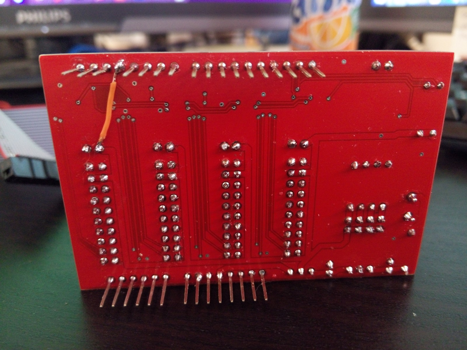
here we are! ![]()
I tried to solder pin 9 with nearest via on pin 3 line but they are too small for solder a wire that can be stay there good, so easiest solution was cut pin 3 and connect a small wire to +5v. Nearest via is +5v bus that arrive at cap on chip 0.
It is not so beautiful, but it works! ![]()
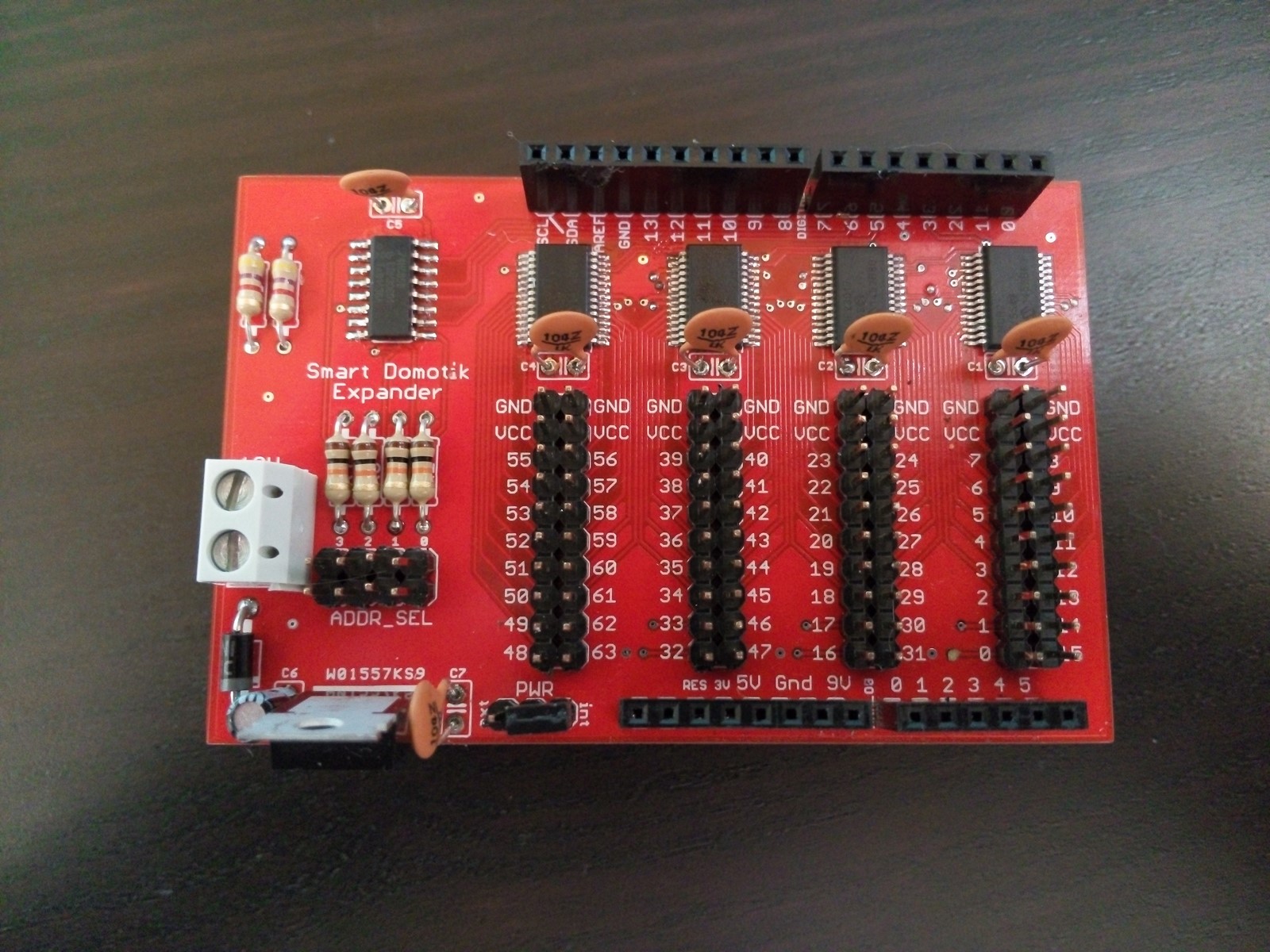
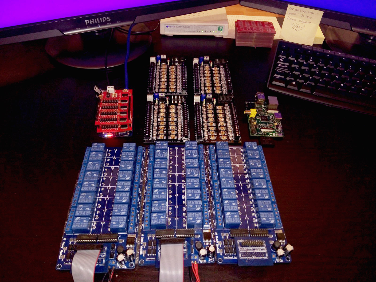
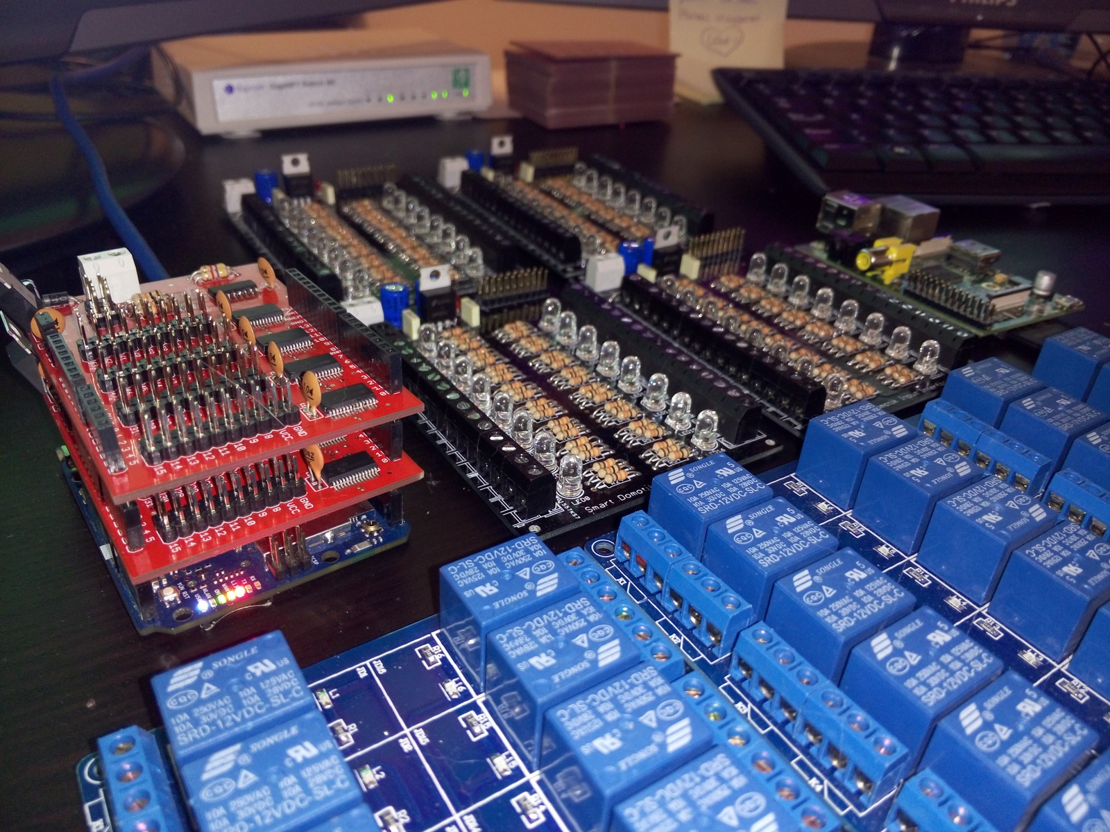
I attached some pics of shield completed, i don't like that type of caps, maybe I'll change in next builds.
This shield looks like a little town ![]()
I tested with centipede library and it works good, now i've to complete my library and make some others deep test.
Thanks to all for big help that you gave me until now!


One question:
In my library i need to set address pin so i use normal digitalWrite, but i think that arduino use digitalWrite of my library instead of "standard" digitalWrite, and it crashes. ![]()
I tried to rename all my library functions to something like prefix_* and all work fine, but is there some other method without rename all my functions and keep standard name using some default function like digitalWrite inside the library?
a simple example:
void SmartDomo_Exp::initialize(uint8_t countShields, uint8_t countOUT_MCP, uint8_t countIN_MCP, uint16_t defaultOutChipValue)
{
  // inizialize address pins
  // here it crash because it use below fuctions instead of default.
  pinMode(addrPIN0, OUTPUT);
  pinMode(addrPIN1, OUTPUT);
  pinMode(addrPIN2, OUTPUT);
  pinMode(addrPIN3, OUTPUT);
  pinMode(resetPIN, OUTPUT);
  digitalWrite(resetPIN, LOW);

  ...............
}

uint8_t SmartDomo_Exp::pinMode(uint16_t logicalPin, uint8_t mode) {
    pin_pos p;
  p = logicToRealPin(logicalPin);
  SelectShield(p.board);
  return WriteRegisterPin(p.chip, p.pin, p.gpio_register, mode ^ 1);

}

uint8_t SmartDomo_Exp::digitalWrite(uint16_t logicalPin, uint8_t level) {
  pin_pos p;
  p = logicToRealPin(logicalPin);
  SelectShield(p.board);
  return WriteRegisterPin(p.chip, p.pin, 0x12 + p.gpio_register, level);
}
leen15:
I attached some pics of shield completed, i don't like that type of caps, maybe I'll change in next builds.
Looks nice! 8) The repair should work well, and looks nicely done.
Yes, those caps are quite large. There's a 1K marking on them, are they rated for 1000 Volts? :o If so, you don't need anywhere near that high of a voltage rating, anything over 15 volts will be more than enough, and they will be physically smaller and fit better. (Of course, the cap on the input of the voltage regulator should be rated higher, the 50V rating on the cap you used looks perfect.)
I notice the markings on the shield connectors of your Yun look like stickers. Interesting, the markings on mine are printed directly on the headers. Obviously, ours were built in different batches.
leen15:
In my library i need to set address pin so i use normal digitalWrite, but i think that arduino use digitalWrite of my library instead of "standard" digitalWrite, and it crashes.
Outside of the class, digitalWrite() will get the "normal" function, unless you are specifically accessing the function defined by the class.
But inside the class, it will assume you want the the one defined by your class. To access a different version of a function with the same name, you have to preface it with the namespace. Since you want the version that is not defined in any class, leave the namespace blank, but you still need the scope resolution operator ( :: ) for example:
::digitalWrite(resetPIN, LOW);
Inside your code, you're using SmarDomo_Exp:: in several places to indicate you mean to use the class's namespace. Just using the double colon by itself with nothing in front of it means you want to reference the global namespace. You only need to do this when working within the class itself, because the local class namespace is assumed. When you are outside of the class, you don't need to do this because the global namespace is assumed.
ShapeShifter:
Looks nice! 8) The repair should work well, and looks nicely done.Yes, those caps are quite large. There's a 1K marking on them, are they rated for 1000 Volts? :o If so, you don't need anywhere near that high of a voltage rating, anything over 15 volts will be more than enough, and they will be physically smaller and fit better. (Of course, the cap on the input of the voltage regulator should be rated higher, the 50V rating on the cap you used looks perfect.)
I just checked in a local electronic store, caps are 50V, and they are the only one with 2.54mm.. I will check online if I will found something smaller! ![]()
For next builds i'll put caps a little more down, I have components for about 4-5 shields, so I need to reorder ![]()
Thanks for library tip, I'll try! ![]()
After some testing, there is something wrong with 74HC85D.
as the datasheet describes (http://www.nxp.com/documents/data_sheet/74HC_HCT85_CNV.pdf), it should take a max of 35 nS to change output value at change of A and B inputs.
But, as show in this video:
It take a lot longer, about 5-6 SECONDS!
for explain a bit, console result is:
PIN - BOARD High/Low result: 0 (ok) / 2 (ko)
Board 1 isn't connected, so it should return always 2.
With multimeter i'm measuring 74HC85D output connected to A2 of every MCP* chip.
When console writes SET SHIELD * code execution is:
void SmartDomo_Exp::SelectShield(uint8_t shieldAddr) {
  // extract bit X from binary value of shieldAddr and so on
  if (lasShieldAddr != shieldAddr)
  {
    Console.print(F("SET SHIELD "));
    Console.println(shieldAddr);
    ::digitalWrite(addrPIN0, (shieldAddr & (1 << (1-1)))?1:0 );
    ::digitalWrite(addrPIN1, (shieldAddr & (1 << (2-1)))?1:0 );
    ::digitalWrite(addrPIN2, (shieldAddr & (1 << (3-1)))?1:0 );
    ::digitalWrite(addrPIN3, (shieldAddr & (1 << (4-1)))?1:0 );
    lasShieldAddr = shieldAddr;
    delay(1000);
  }
}
I added also a delay of 1 SECOND but it doesn't change a lot..
I tried to measure addrPIN0 that is the only one that should change from 0 to 1 when changing the board and it's value change immediately, so is 74HC85D so slow? ![]()
Just tried with another board, and works fine.. so there is something wrong with that 74HC85D. I'll try to change it! ![]()
As a kid, I was always playing with electronics and building circuits. There was no question I wanted to be an electrical engineer. Then, while at university, was first exposed to computers - pretty interesting. I was on a co-op work/study plan where I spent 6 months in school, and six months working in industry. My first work cycle, I was doing strictly electronics, which was OK. My second cycle was mostly software, which I liked. My third started out by designing a board and finished with programming it - the work on the board was OK but tedious, but the software was really fun. When I came back from that work cycle, I changed majors from electrical engineering to computers.
The main reason: I don't like checking out hardware. OK, that's not quite right: it's fun getting the first board to work. But what I hate is that every board needs the same amount of work to check out and debug. That really wears me down, and that's exactly what you're running into now. I feel your pain!