CrossRoads:
3 discrete diodes connected in parallel to make up the segments of each 7-segment display.
G Mike will not appreciate that!
CrossRoads:
3 discrete diodes connected in parallel to make up the segments of each 7-segment display.
G Mike will not appreciate that!
Worked well for 10 years; between LEDs bought in one batch and the MAX7219 controlling the current out of it's segment pins, there has not been an issue.
As an experience..let see.. 
I know soldering stranded and solid wires.
My bigest project in electric are instalation of video survilence on my house  Also there was a building electric skateboard too.. some other little stuf...
Not worked with wirewraps in past. Not sure how to use it. I must see some tutorials.
I am better on soldering at stripboards.
If you have the experience in soldering, I see no reason to go to WireWrap. It is seriously not good where you need to make modifications.
If you will not be altering the design, or moving parts back and forth during assemble, solid core wire (which is most certainly what WireWrap is) would be OK.
One trick about WireWrap, is that the first part of the wrap includes the insulation on the wire. This avoids a point of weakness where the insulation is not reinforcing the bared wire at the point of termination.
"WireWrap. It is seriously not good where you need to make modifications."
I 100% disagree with that. It is also waaay easier to make changes then trying to unsolder something and resolder it and have the insulation melt off and make a mess.
Pictures & link to more info
http://www.gammon.com.au/forum/?id=11109
From Wikipedia: Wire wrapping is unusual among other prototyping technologies since it allows for complex assemblies to be produced by automated equipment, but then easily repaired or modified by hand.
I've done lots of that, especially in the box above, where I changed functionality as I figured out what I wanted the box to do.
fixed the link Gammon Forum : Electronics : Microprocessors : Minimal circuit for Atmega328 processor (shows wire-wrapping)
I used to wirewrap many years ago, then abandoned it for soldering.
But as old age hits and eyesight gets worse, wirewrap is actually easier.
Quoting from PMs:
danyCro:
Hi Paul. This forum is sucks because I can't add picture without a link!
Sorry for delay, I dont have time at home, and waitng every package for 30-60 days..I got some boards, what you think about that?
At first at all, please explain me to understand this max7219.
There is two parts, do I need join that parts like this or not?
Paul__B:
OK, you appear to have some prototyping board which has individual pads for each perforation. That is usable for the job but not quite as convenient as "stripboard" which has as the name, strips of copper joining multiple holes so that you can solder one wire or component pin in each hole. You can however use it as stripboard by soldering the wires and component pins in adjacent holes and then using enough solder to bridge those adjacent pads.
Now those MAX7219 modules come as the IC mounted to a PCB for your convenience, and a LED matrix. If the matrix is what you wanted to use, then you would solder the socket pins to the board and then plug in the matrix. But you do not want to use the matrix; it becomes a spare part. You just identify which pads correspond to which pins of the MAX7219 (by knowing the pin-out of the matrix as below) and connect them to the appropriate pins of your seven-segment LEDs with your ribbon wire.
You probably want to use one ribbon for the common cathodes where one wire goes to each display - this will end up as separate wires - and one ribbon for the anodes which goes to each display and chains on to the next.By the way, you can test the pin-out of the matrix itself with a 5 V supply, a 1k series resistor and jumper wires (preferably male-female "Dupont" wires and a breadboard - or just the breadboard and some non-stranded jumpers). Remember that pins are numbered clockwise looking from underneath the component.
danyCro:
Sorry for the mess, but my solder iron is big and solder wire is 1.5. That will be a "rough" and first test. My new toll with wire 0.6 is on the way...
Don't worry, I tested all rows wit multimeter to be shure that avoid short circuit between displays Weires.You see, only 3 wires now going to max7219 (I will add all later), and my main question will be: is important from which displays wires goes to Max7219?
On my example from display 1 goes blue wire, and from display 3 going purple and brown wires. Is that good and can I continue with that way?
I do that because easiest solding.
Whoah!
If you are using stripboard like that, you want to run the connecting wires on top of the board and use a separate hole for each wire. That makes the soldering much easier. For the links from one display to the next, since you are never going to move them after fitted, you can use single stand wire (telephone cable wire is good) with less bulky insulation than the flexible wire, so the fact that they have to bunch together as in this picture, is less of a problem.

In fact, using the single stand wire, you can run at least some of the connecting wires (there are after all, only four per side) under the display - you fit the wire first and then solder the display on.
Your wiring in your picture is wrong! You have connected all the wires to each display together - five on top and five on the bottom. Too many wires! Unless I am wrong, the middle wire in each row is the common cathode (and the top and bottom are already connected together) - this wire - only one, either top or bottom - is the separate wire to a cathode driver pin on the MAX7219 board.
You need to get one set of three displays wired, connect it to the MAX7219 board and test it out (with some code of course) before going any further.
I should also point out that notwithstanding any embarrassment, I am putting this discussion on your original thread on the forum itself as the construction is now a rather complex project and I hope other people can help (and/ or learn!) 
You need to cut the coppertraces between the display pins.
I not connected middle point which will be VCC on my Common Anode.
These pins are used to select the digit that lights up. Connect these to their individual anode pin of the LED driver.
Rintin:
You need to cut the coppertraces between the display pins.
That was a diagram - they are not real wires - yet!
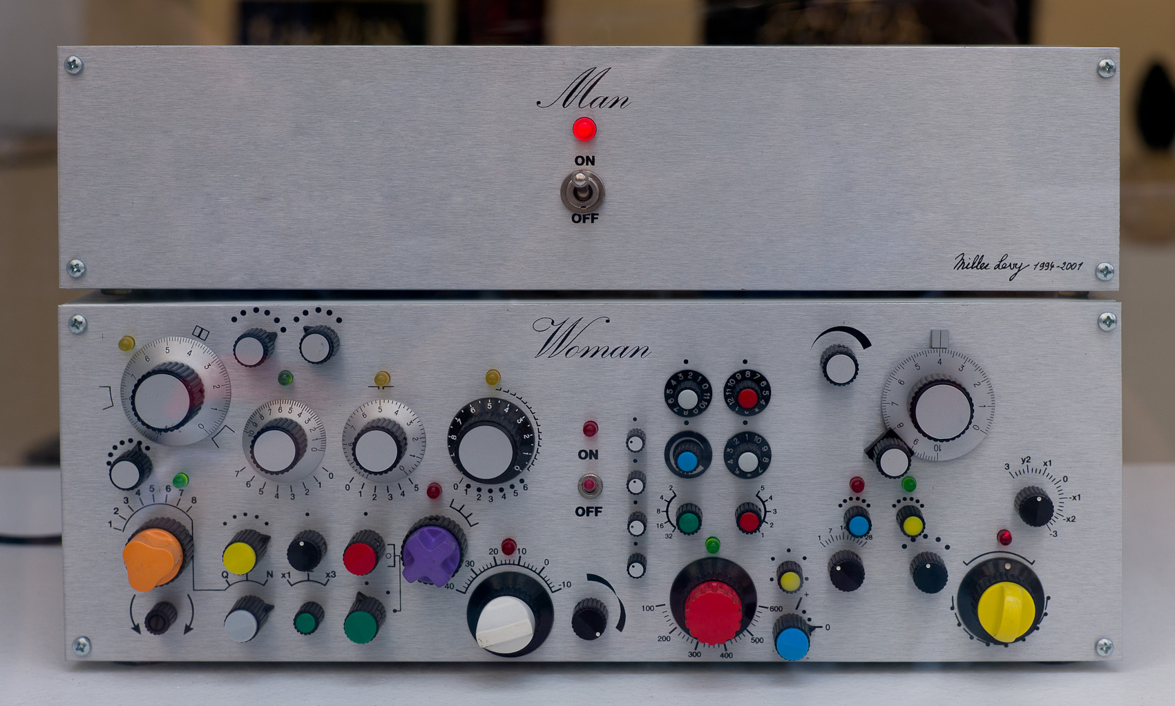
That picture in the Original Post reminds me of this: