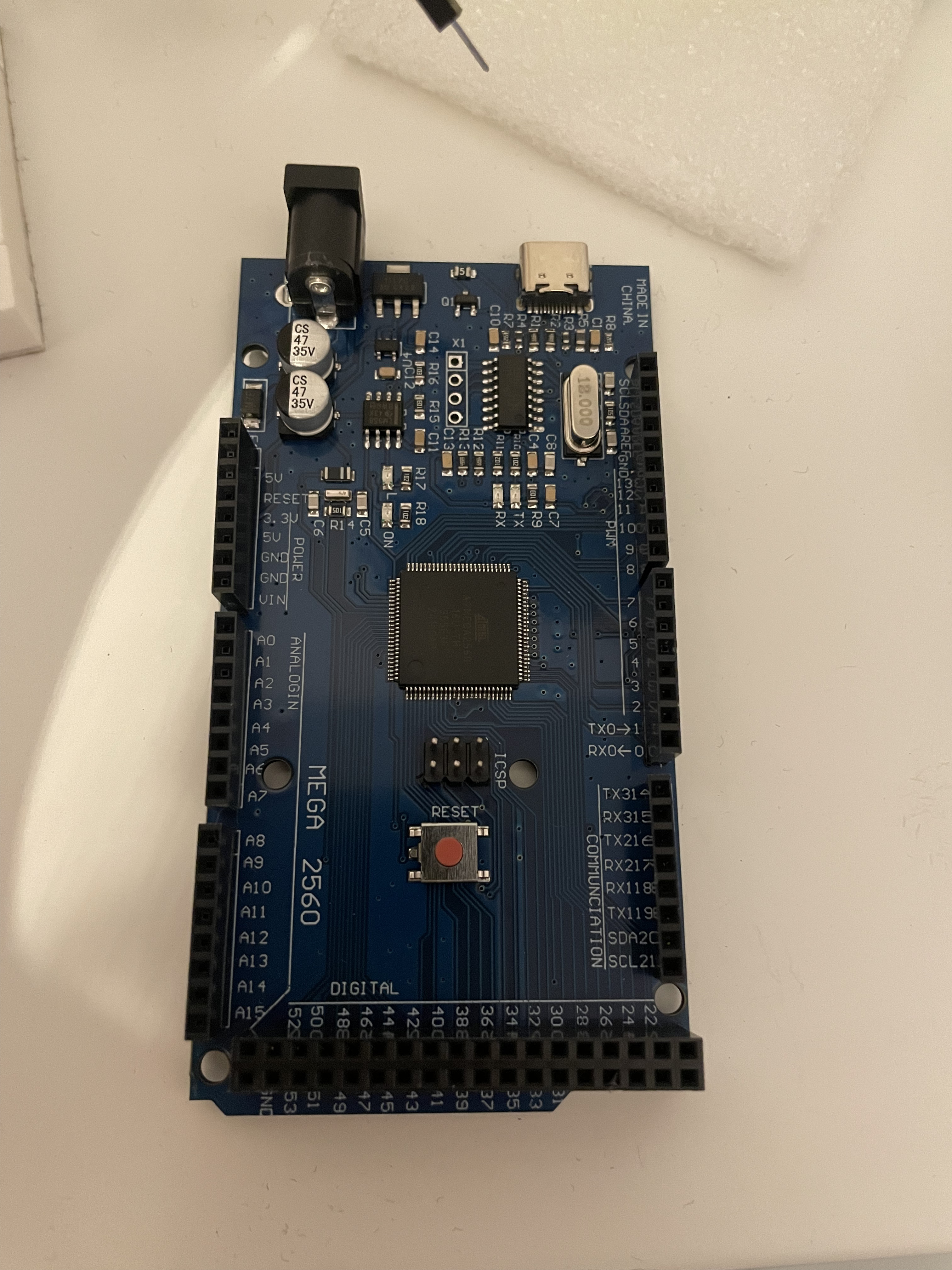
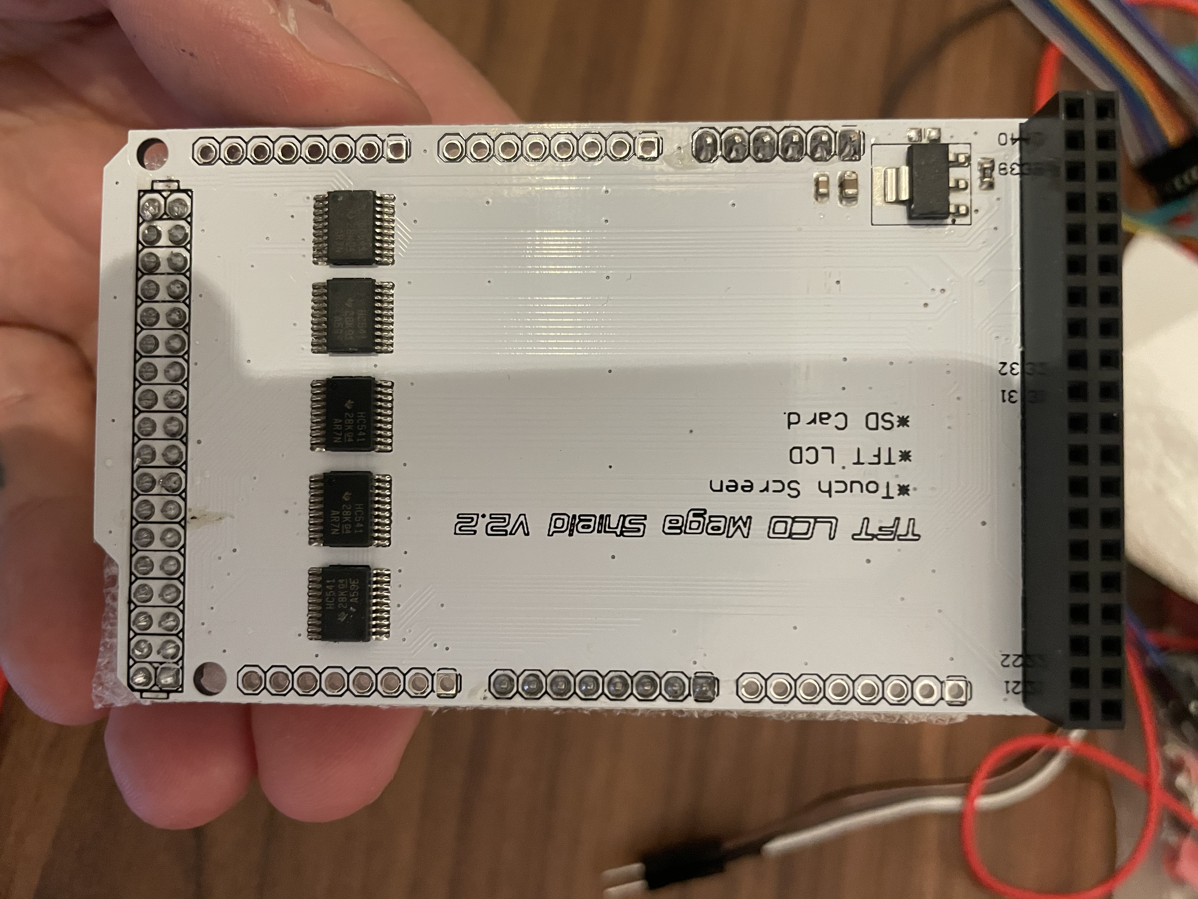
Hi everyone. I've been going crazy for days trying to get this 7'' display to work with an Arduino Mega 2560. First, I tried connecting it via breadboard and jumper wires, then I bought a shield, but it didn’t change anything. In fact, the screen doesn’t show any signs of life at all, whereas with the wires at least the backlight would turn on. Attached are the photos of the components I have available. I’d prefer to find a way to make it work without the shield.
I’ve tried several libraries, from UTFT master to MCUFRIEND to Adafruit, but I haven’t been able to get the Arduino to communicate with the screen in any way.
Can someone give me some detailed help? I’m not very experienced, but I can manage some things—this just seems impossible. Thank you so much!
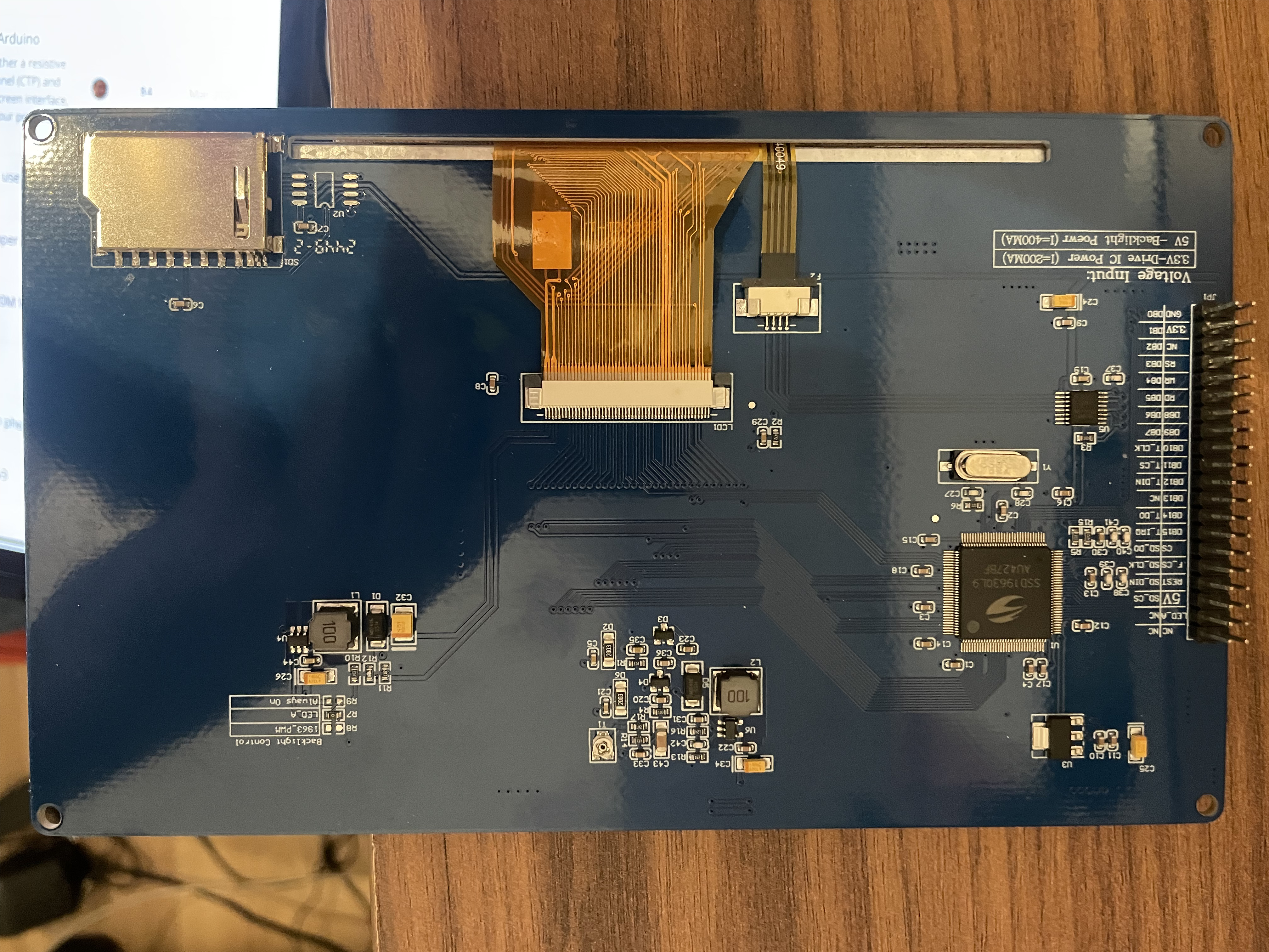
Looking at the display - which uses 3.3v - I'd say you need to use either the shield or the equivalent of the shield. It looks like the shield is providing the level translation from the 5V MEGA2560 board to the 3.3v logic levels that the display wants - so you might as well use the shield as you have it already!
Have a read of this discussion, which may help you out:
I have the impression that the shield is not working properly because, for example, when I measure pin 2 of the shield with the multimeter, it outputs 5V, while the display pin that connects there is supposed to receive 3.3V.
Yes, I also read that discussion, but it's not very helpful.
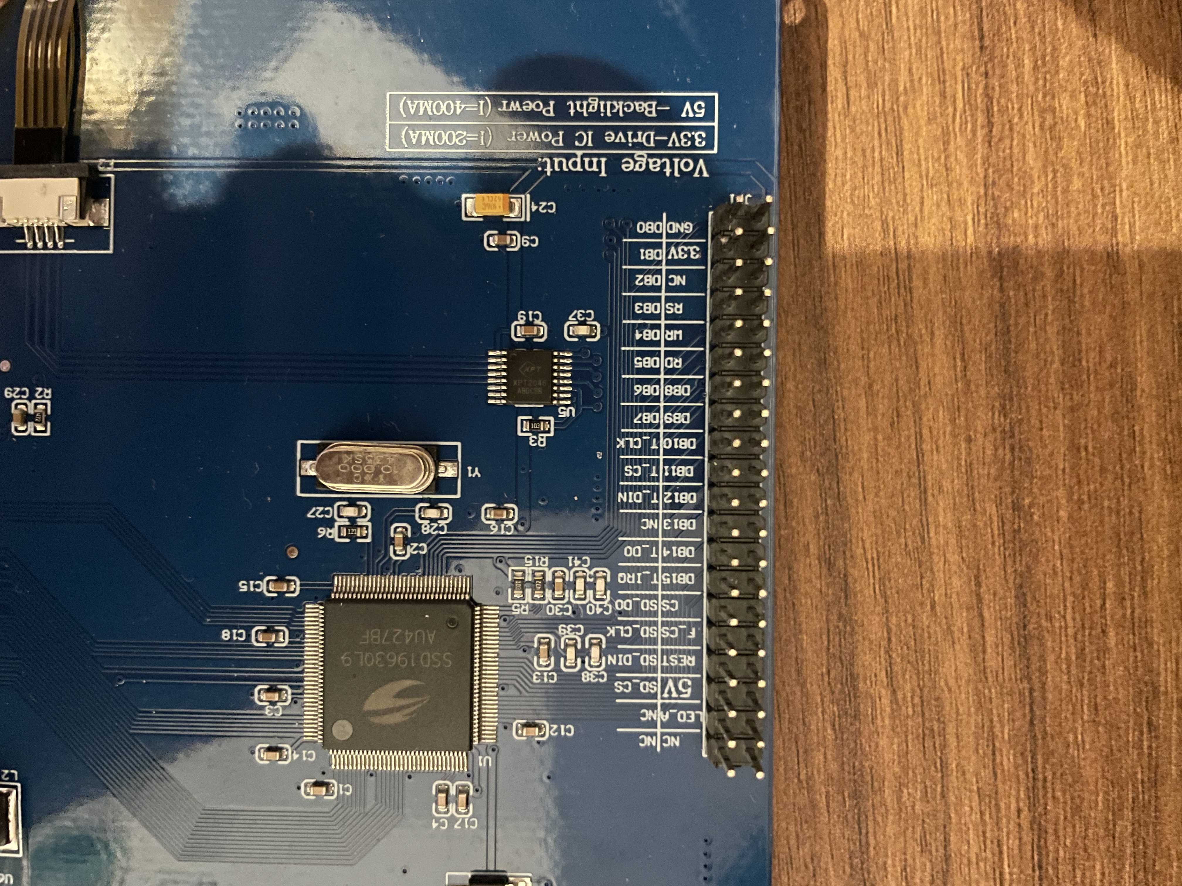
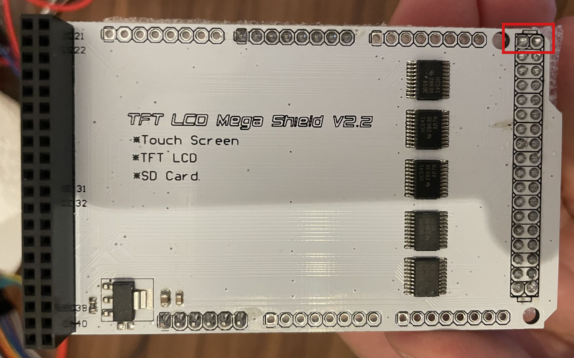
The only pin numbering is on the left hand connector in the image above indicating pins 21 -> 40.
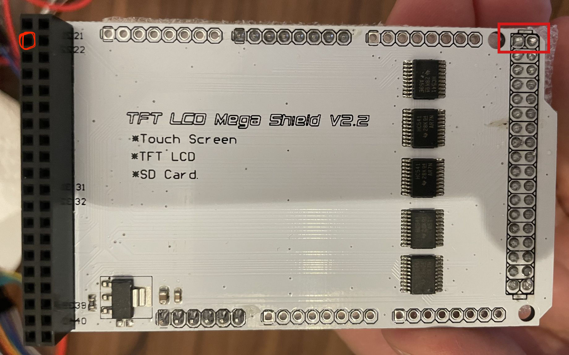
Are you referring to one of the 2 pins I have highlighted in the red box - top right hand corner? If you are, then they are both supposed to read 5V - supplied from the MEGA2560.
The second pin on the left I've highlighted.
I've tried to connect with wires withous connecting pin 2, anche the LCD is white without receiving any input from UTFT master library
UTFT myGLCD(SSD1963_800,38,39,40,41);
I also found the TFT V2.2 scheme below that confirm 5V from pin2 TFT_Mega_Shield_V2_2.pdf (1.5 MB)
Ah, I see now. That does contradict what the TFT expects on that pin. Perhaps the question now is whether the shield is the correct one for the TFT you have?
It seems to me that it's supposed to be compatible with this type of screen... but maybe not. Anyway, I added a resistor on that pin and now the screen does turn on — everything is wired correctly — but it stays white (not bright, but very faint), and the Arduino is no longer detected by the IDE, it only powers the screen. I'm wondering if there's something wrong with the Arduino or the screen, because the cable connections are correct and all the pins match the ones used by the library...
That would suggest that maybe the screen / shield is drawing too much power from the MEGA2560 board - possibly as a result of the mismatch between the shield and the TFT.
The Arduino boards are not meant to be a power source for other devices - especially anything power hungry. The rear of the TFT in your photo indicates that it requires 400mA @ 5V for the backlight and 200mA @ 3.3V for the display.
I would think that is exceeding the capabilities of the MEGA2560. Additionally, I seem to recall that USB2 (assuming you are powering from the USB connector) has a limit of 500mA per device.
You're right, but on internet I found this: "On board 400mA DC-DC Boost regulator to provide power supply to LCD backlight"
Anyway right now I'm using an external power supply connected to 5V pin and LED_A on the display (with GND in common between supply, arduino, shield). The screen is bright, and Arduino still not being recognized on the IDE...
The power for that has to come from somewhere - which would be the MEGA2560 via either the USB connector or the external power connector.
I would disconnect everything from your MEGA2560 and see if it is detected by your PC and the IDE just to confirm that your MEGA2560 is still ok. It may well be that the TFT & shield are collectively drawing too much power from the MEGA2560 causing the on-board regulator to shut down.