//......................................................................................................................................................
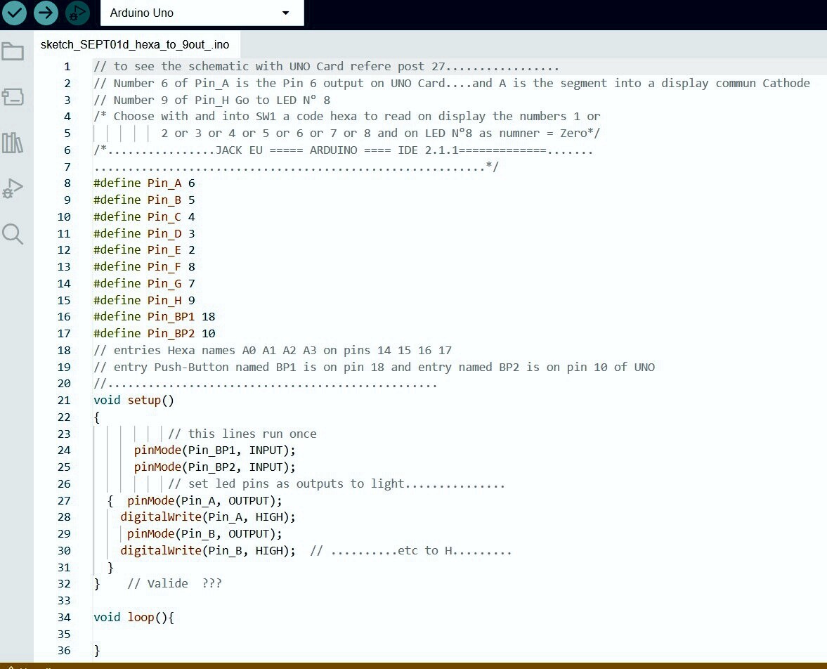
// The schematic for this sketch is on Post n°27. Common cathode UNO 4 IN 8 OUT Aug 26th 2023
//......
// Read conditions at start of void loop
// The display has seven segment and to see the eighth output there is a Led, LED 8
// I can read on display number one to eight and with this led 8, it's A with pin 9 output.
# define Pin_A 6
# define Pin_B 5
# define Pin_C 4
# define Pin_D 3
# define Pin_E 2
# define Pin_F 8
# define Pin_G 7
# define Pin_H 9

// now BP1 and BP2 Push Buttons, see the schematic Post N°27
#define Pin_BP1 18
#define Pin_BP2 10

void setup()
{
// set LED pins as output to light, by defaut they output LOW
pinMode (Pin_A,OUTPUT);
digitalWrite(Pin_A, HIGH);
pinMode (Pin_B,OUTPUT);
digitalWrite(Pin_B, HIGH);
pinMode (Pin_C,OUTPUT);
digitalWrite(Pin_C, HIGH);
pinMode (Pin_D,OUTPUT);
digitalWrite(Pin_D, HIGH);
pinMode (Pin_E,OUTPUT);
digitalWrite(Pin_E, HIGH);
pinMode (Pin_F,OUTPUT);
digitalWrite(Pin_F, HIGH);
pinMode (Pin_G,OUTPUT);
digitalWrite(Pin_H, HIGH);
pinMode (Pin_H,OUTPUT);
// digital input for BP1 on entry A4(pin18), and digital input BP2 on entry
// D10 on the Uno board
//........................................................................................................................
}

void loop()
// read voltage on Button PB1to valid, and, BP2 to erase or reset ,  the
// levels into SW1 are no operande
// When there is a number on display and Led 8, you can
// use BP2 to erase all leds. And after you can choose a code Hexa with
// switches into SW1.
// this code will be memorize in UNO When you push on BP1.
// if you change the code Hexa without erase with BP2, this code will not be
// memorized in Uno, even if you press on BP1.

{
        bool button_PB1= digitalRead(18);  //   18 or A4 ?
        bool button_PB2= digitalRead(10);
// if the PB2 "erase reset" is pressed (connect to GND)
       if(button_BP2 ==LOW)
           {
// set the LED pins to LOW voltage level (no current flow, no light).
              digitalWrite(Pin_A, LOW);
              digitalWrite(Pin_B, LOW);
              digitalWrite(Pin_C, LOW);
              digitalWrite(Pin_D, LOW);
              digitalWrite(Pin_E, LOW);
              digitalWrite(Pin_F, LOW);
              digitalWrite(Pin_G, LOW);
              digitalWrite(Pin_H, LOW);
//   digital input for BP1 on entry A4, Pin 18;   and digital input BP2 on entry
//   D10 Pin 10 on the Uno board


         }
// to be continued
}
Hello toddnz,
I have fixed my mistakes in this sketck.
This Post n°42 will be completed day after day.
to be contined
Best regards, JACK