Hello toddnz
I have worked on the sketch, there is a problem wiith hexa letters A at F to memorizate it.
See the // after number 9.
Ihope yours informations, Thanks ;
here the sketch compiled ok
saisissez ou collez du code ici
// NO date no finished
// NO VALIDED
// to see the schematic with UNOR3 Card refere post 27.................
// Number 6 of Pin_A is the Pin 6 output on UNO Card....and A is the segment into a display commun Cathode
// Number 9 of Pin_H Go to LED N° 8 used to verify number zero ok
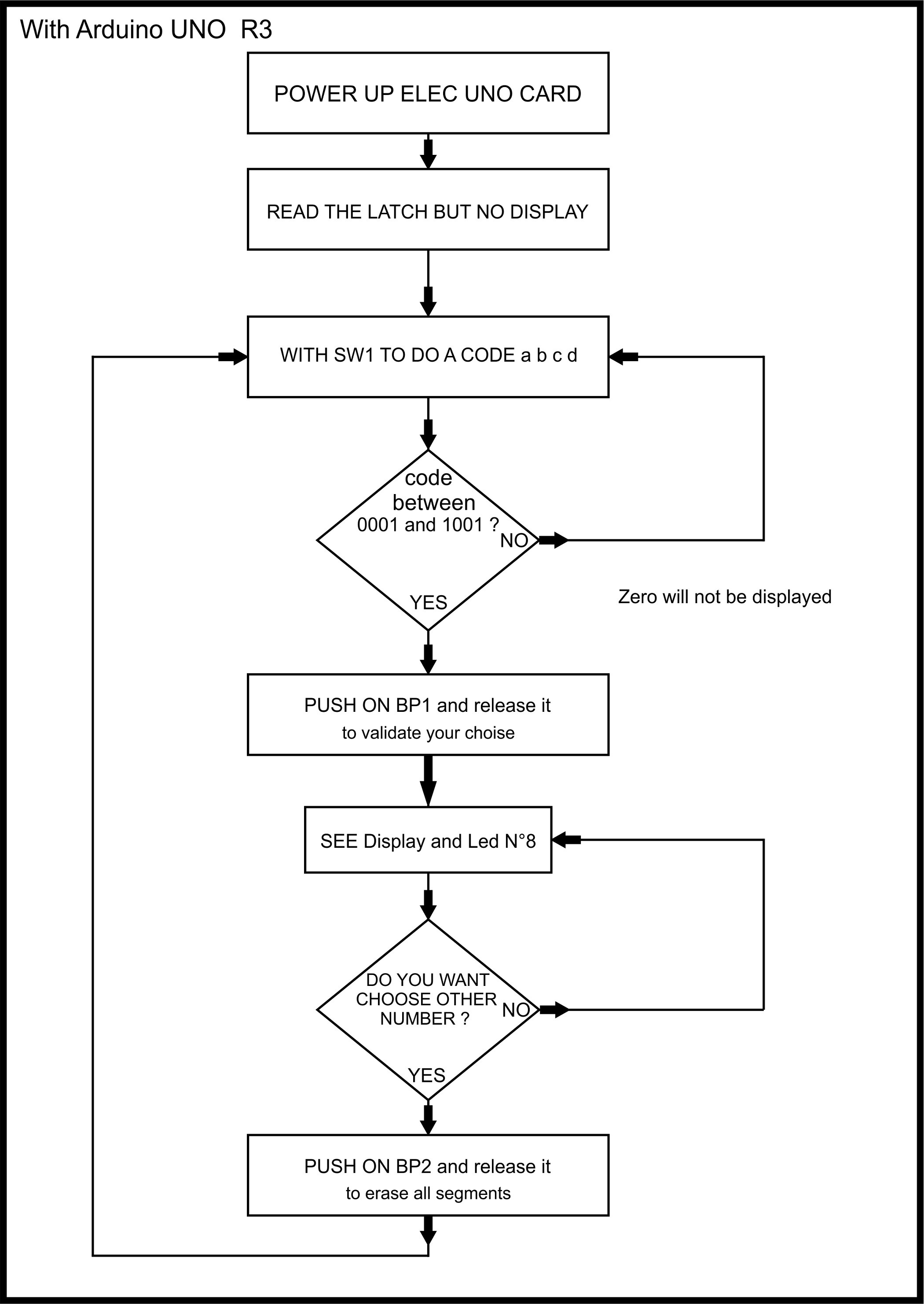
/* Choose with and into SW1 a code hexa to read on display the numbers 1 or
2 or 3 or 4 or 5 or 6 or 7 or 8 or 9
and letters A to F, and on LED N°8 as verification number = Zero*/
/*................JACK EU ===== ARDUINO ==== IDE 2.1.1=============.......
..........................................................*/
#define Pin_A 6
#define Pin_B 5
#define Pin_C 4
#define Pin_D 3
#define Pin_E 2
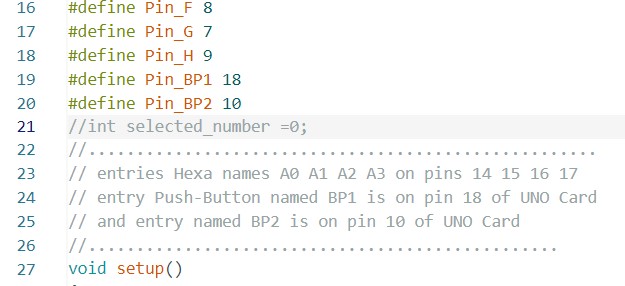
#define Pin_F 8
#define Pin_G 7
#define Pin_H 9
#define Pin_BP1 18
#define Pin_BP2 10
int selected_number =0;
//................................................................
//................................................................
// entries Hexa names A0 A1 A2 A3 on pins 14 15 16 17
// entry Push-Button named BP1 is on pin 18
// and entry named BP2 is on pin 10 of UNO
//.................................................
void setup()
{
// this lines run once
pinMode(Pin_BP1, INPUT);
pinMode(Pin_BP2, INPUT);
// set led pins as outputs to light...............
pinMode(Pin_A, OUTPUT);
digitalWrite(Pin_A, LOW);
pinMode(Pin_B, OUTPUT);
digitalWrite(Pin_B, LOW);
pinMode(Pin_C, OUTPUT);
digitalWrite(Pin_C, LOW);
pinMode(Pin_D, OUTPUT);
digitalWrite(Pin_D, LOW);
pinMode(Pin_E, OUTPUT);
digitalWrite(Pin_E, LOW);
pinMode(Pin_F, OUTPUT);
digitalWrite(Pin_F, LOW);
pinMode(Pin_G, OUTPUT);
digitalWrite(Pin_G, LOW);
pinMode(Pin_H, OUTPUT);
digitalWrite(Pin_H, LOW);
} // ......................END SETUP ...................
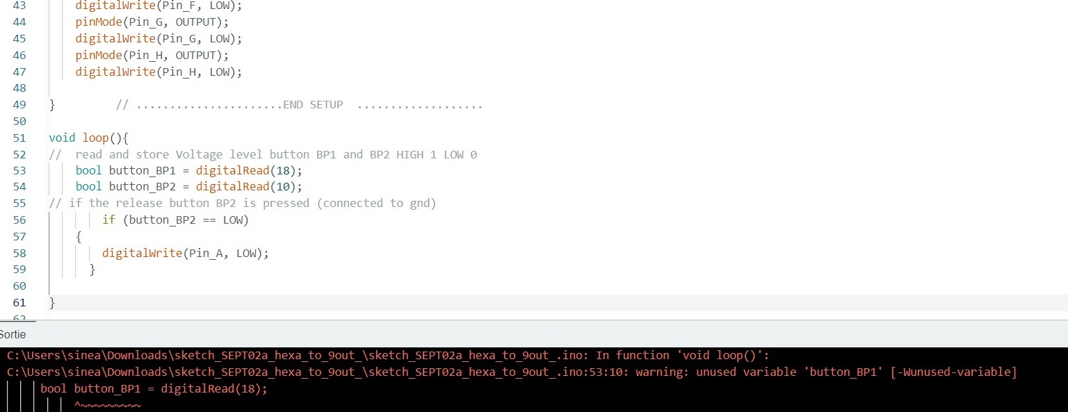
void loop(){
// read and store Voltage level button BP1 and BP2 HIGH 1 LOW 0
bool button_BP1 = digitalRead(18);
bool button_BP2 = digitalRead(10);
//bool button_BP1 = digitalRead(18);
// if the release button BP2 is pressed (connected to gnd)
if (button_BP2 == LOW)
{
digitalWrite(Pin_A, LOW);
}
// if the valid selection BP1 is pressed level is LOW
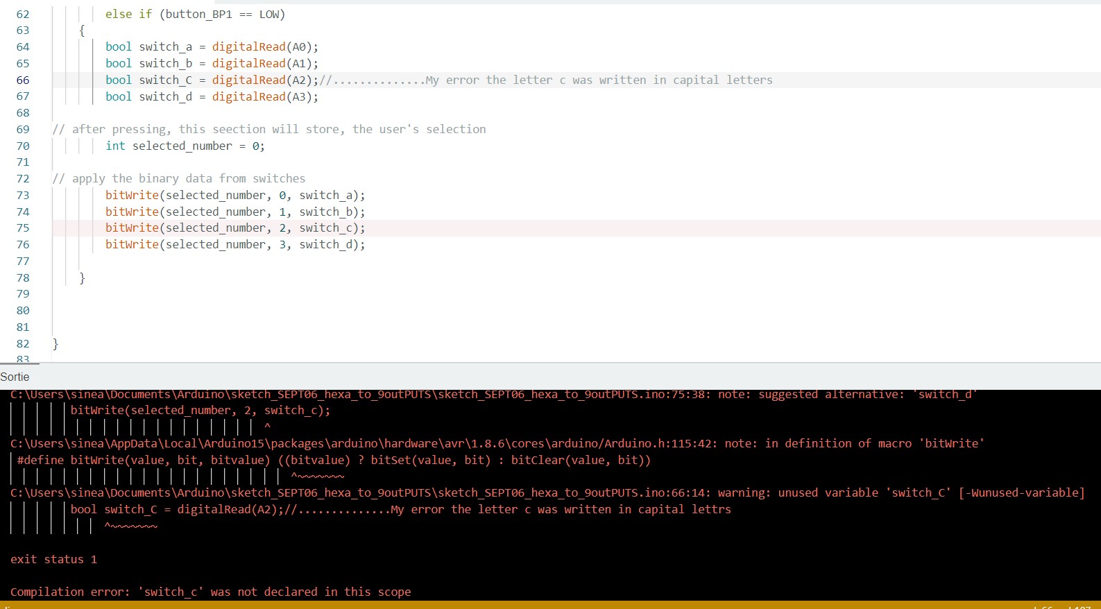
else if (button_BP1 == LOW)
{
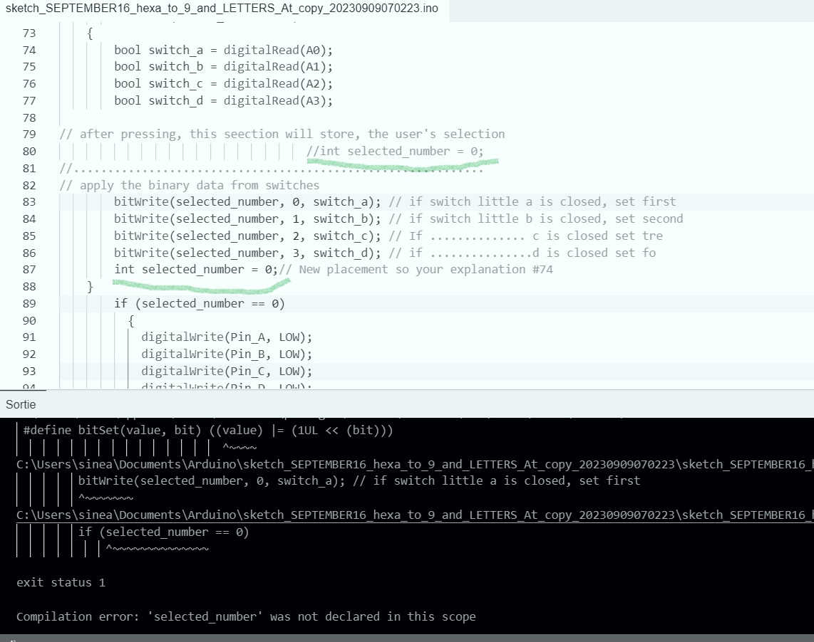
bool switch_a = digitalRead(A0);
bool switch_b = digitalRead(A1);
bool switch_c = digitalRead(A2);
bool switch_d = digitalRead(A3);
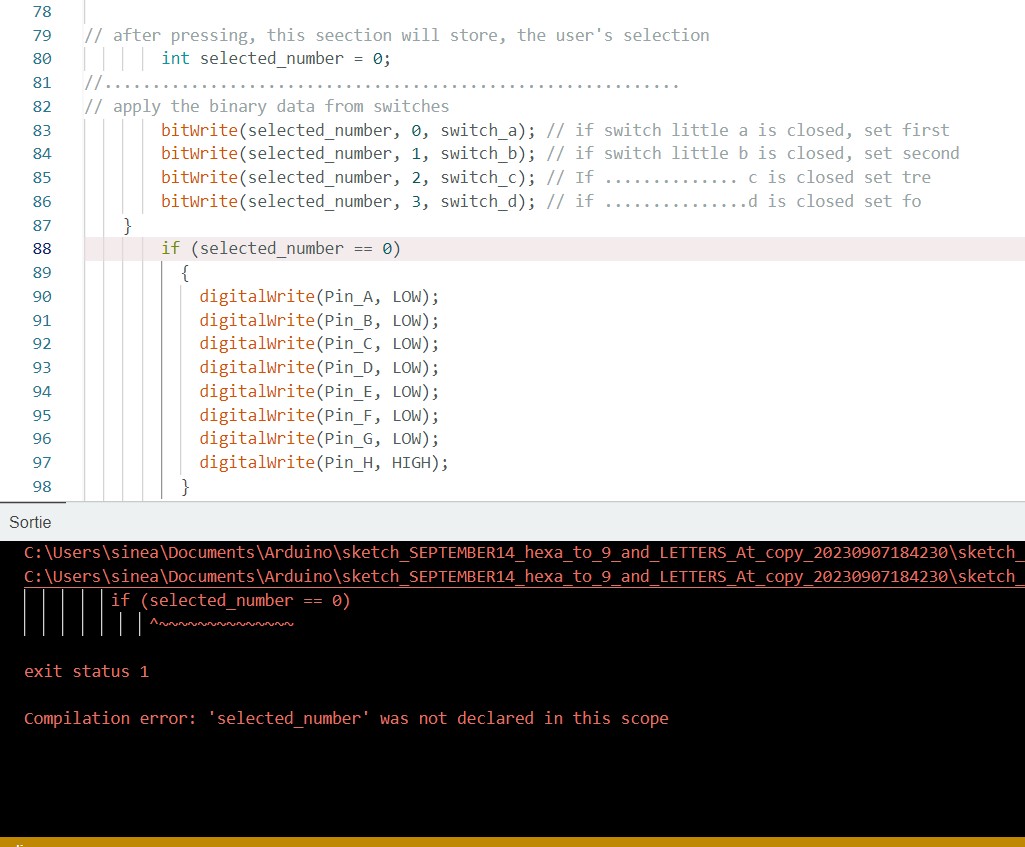
// after pressing, this seection will store, the user's selection
int selected_number = 0;
//int selected_letter = 0;
// apply the binary data from switches
bitWrite(selected_number, 0, switch_a); // if switch little a is closed, set first
bitWrite(selected_number, 1, switch_b); // if switch little b is closed, set second
bitWrite(selected_number, 2, switch_c); // If .............. c is closed set tre
bitWrite(selected_number, 3, switch_d); // if ...............d is closed set fo
}
if (selected_number == 0)
{
digitalWrite(Pin_A, LOW);
digitalWrite(Pin_B, LOW);
digitalWrite(Pin_C, LOW);
digitalWrite(Pin_D, LOW);
digitalWrite(Pin_E, LOW);
digitalWrite(Pin_F, LOW);
digitalWrite(Pin_G, LOW);
digitalWrite(Pin_H, HIGH);
}
else if (selected_number == 1)
{
digitalWrite(Pin_B, HIGH);
digitalWrite(Pin_C, HIGH);
}
else if (selected_number == 2)
{
digitalWrite(Pin_A, HIGH);
digitalWrite(Pin_B, HIGH);
digitalWrite(Pin_D, HIGH);
digitalWrite(Pin_E, HIGH);
digitalWrite(Pin_G, HIGH);
}
else if (selected_number == 3)
{
digitalWrite(Pin_A, HIGH);
digitalWrite(Pin_B, HIGH);
digitalWrite(Pin_C, HIGH);
digitalWrite(Pin_D, HIGH);
digitalWrite(Pin_G, HIGH);
}
else if (selected_number == 4)
{
digitalWrite(Pin_B, HIGH);
digitalWrite(Pin_C, HIGH);
digitalWrite(Pin_F, HIGH);
digitalWrite(Pin_G, HIGH);
}
else if (selected_number == 5)
{
digitalWrite(Pin_A, HIGH);
digitalWrite(Pin_F, HIGH);
digitalWrite(Pin_G, HIGH);
digitalWrite(Pin_C, HIGH);
digitalWrite(Pin_D, HIGH);
}
else if (selected_number == 6)
{
digitalWrite(Pin_F, HIGH);
digitalWrite(Pin_E, HIGH);
digitalWrite(Pin_D, HIGH);
digitalWrite(Pin_C, HIGH);
digitalWrite(Pin_G, HIGH);
}
else if (selected_number == 7)
{
digitalWrite(Pin_A, HIGH);
digitalWrite(Pin_B, HIGH);
digitalWrite(Pin_C, HIGH);
}
else if (selected_number == 8)
{
digitalWrite(Pin_A, HIGH);
digitalWrite(Pin_B, HIGH);
digitalWrite(Pin_C, HIGH);
digitalWrite(Pin_D, HIGH);
digitalWrite(Pin_E, HIGH);
digitalWrite(Pin_F, HIGH);
digitalWrite(Pin_G, HIGH);
}
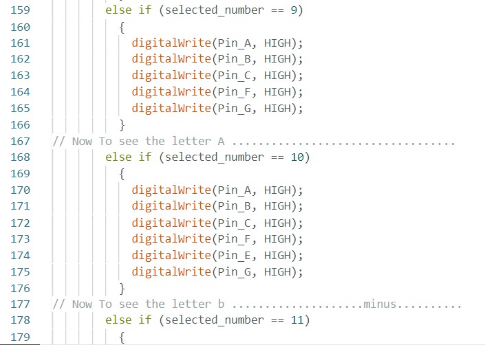
else if (selected_number == 9)
{
digitalWrite(Pin_A, HIGH);
digitalWrite(Pin_B, HIGH);
digitalWrite(Pin_C, HIGH);
digitalWrite(Pin_F, HIGH);
digitalWrite(Pin_G, HIGH);
}
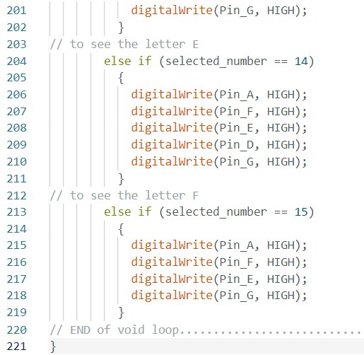
// Now To see the letter A ......................................
else if (selected_number == A7) // .............WHY A7 ? ......
{
digitalWrite(Pin_A, HIGH);
digitalWrite(Pin_B, HIGH);
digitalWrite(Pin_C, HIGH);
digitalWrite(Pin_F, HIGH);
digitalWrite(Pin_E, HIGH);
digitalWrite(Pin_G, HIGH);
}
// Now To see the letter b ....................minus....................
else if (selected_number == B0) // ..............WHY BO ? .........
{
digitalWrite(Pin_F, HIGH);
digitalWrite(Pin_E, HIGH);
digitalWrite(Pin_D, HIGH);
digitalWrite(Pin_C, HIGH);
digitalWrite(Pin_G, HIGH);
}
}