Also, you should be aware that 74LS-series have inputs that "float high."
So in the picture above (assuming the switch connects to an input), when the switch is pushed the input is forced high by the current through the switch, but when the switch ISN'T pushed, the input floats high. The output will always be low...
And the LEDs are backward - you moved the power-side lead from +V to GND, but that's the anode so it needs to be at the higher voltage.
And there should be current-limiting resistors...
a 74LS04 will light up an LED in both states, just fine.
westfw:
Also, you should be aware that 74LS-series have inputs that "float high."
So in the picture above (assuming the switch connects to an input), when the switch is pushed the input is forced high by the current through the switch, but when the switch ISN'T pushed, the input floats high. The output will always be low...
Adding a pulldown resistor to the switch-input does not work. I am going to believe that it is simply not possible because either the current is not enough or the inputs are "open emitters", maybe both.
The 74HC04 seems to offer 50mA Current compared to the 74LS04 which offers -0.4mA.
King_bob:
The 74HC04 seems to offer 50mA Current compared to the 74LS04 which offers -0.4mA.
I cannot see in the datasheet anywhere where you can interpret "to offer 50mA Current".
Perhaps more to the point, how about you explain exactly what it is you want to do with such a circuit and why a logic IC has anything to do with it, before we spend further effort advising?
I have never read an Arduino forum thread with so much bad information in it.
the 74LS04 has not got an open collector output.
like all LS logic if nothing is connected to an input it “floats” high, so connecting an input through a switch to 5V will do sod all.
The 74HC04 seems to offer 50mA Current compared to the 74LS04 which offers -0.4mA.
Is a total nonsense.
Adding a pulldown resistor to the switch-input does not work.
Yes it does, only if you actually read the spec of what constitutes a logic zero you can calculate that you need a resistor smaller than about 220R to effect a pull down.
Grumpy_Mike:
4) Yes it does, only if you actually read the spec of what constitutes a logic zero you can calculate that you need a resistor smaller than about 220R to effect a pull down.
You are correct, a 220 pull down works. Could you please tell me how you calculated/got to this conclusion?
To calculate the pull-down value for LS logic, you divide the maximum permissible "LOW" voltage VIL (0.8 V) by the maximum pull-down current IIL (1.6 mA) to give a value of 500 Ohms. 470 Ohms is commonly used.
However Mike is using an "anti-fudge" (safety) factor of 2¼.
Or actually, now that I check, he is actually using the VIL value of 0.4 V instead, which corresponds to the older 7400 series logic.
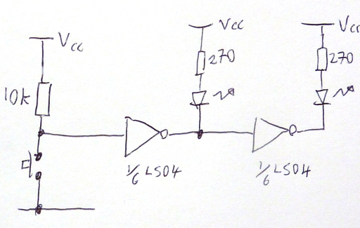
We don't know the details of your project, but if you have several unused inverters and you need logic 1 to illuminate the LED, logic 0 to turn it off, then yeah, this is possible.
For each LED:
Connect 2 inverters in series
Connect the led so its always on: 5V > R > +LED- > GND
Connect the LED anode to the output of the second inverter
Of course, if using only one inverter, logic 1 turns off the LED, logic 0 illuminates it.
I am using it to modify a GRBL Shield, in order to manually Disable/enable the steppers one at a time. The inverse logic is to enable the stepper driver (LOW) while turning on an LED (HIGH) and vice versa.
King_bob:
The working circut: I am using it to modify a GRBL Shield, in order to manually Disable/enable the steppers one at a time. The inverse logic is to enable the stepper driver (LOW) while turning on an LED (HIGH) and vice versa.
I'm late to the thread. But in many circumstances you would not need any IC at all to do that. Usually you can add an indicator LED directly to an enable line, if the LED current is not excessive. If your enable line is active low, you can wire the LED cathode to the enable line, and the anode to a resistor connected to Vcc. Some boards have that circuit on the onboard LED. The pin that is connected to it is still usable for output.
King_bob:
You said nothing about this. Please explain if you are going to bring up a different solution.
Not me but others, I had assumed you were taking notice.
From reply #2
You MUST put resistors in series with your LEDs, about 220 Ohms or so. You have probably popped the LED connected to the button.
From reply #28
We don't know the details of your project, but if you have several unused inverters and you need logic 1 to illuminate the LED, logic 0 to turn it off, then yeah, this is possible.
For each LED:
Connect 2 inverters in series
Connect the led so its always on: 5V > R > +LED- > GND
Connect the LED anode to the output of the second inverte
One of the rules of TTL is never connect an input to Vcc directly, always use a series resistor.
This is because the inputs will fry at just over 5V, which is far too close to Vcc for safety.
TTL is dead in the water as a technology, though you can still buy 74xx and 74LSxx chips
for legacy repairs.
Much much better to use CMOS, like 75HC04
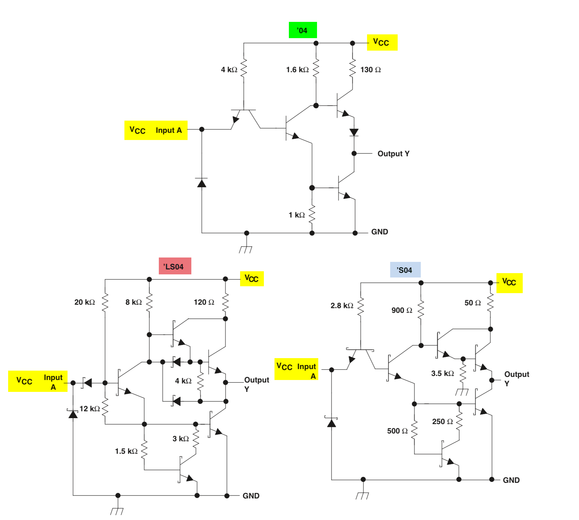
However as we are talking TTL, specifically LS TTL:
Inputs that are not from another gate should either connect to ground or to a ~10k resistor to Vcc.
Typically a switch would be wired to ground with a 10k pull-up resistor to meet this constraint.
LS TTL can only sink useful amounts of current, so LEDs/resistors are wired between an output
and Vcc, not between the output and ground....
I think if I remember that far back the sourcing current is limited to a few 100µA, basically nothing!
TTL outputs do not rise much above 3.5V... Not enough voltage to drive a white LED to ground
anyway, even if it could provide enough current.
TTL totem pole outputs are not symmetric like CMOS ones. You can view a TTL output as open
collector plus a pull-up resistor built in, and you'd not be far wrong.
[ Here's how to do it:
Don't forget supply decoupling as required by any logic chip ]