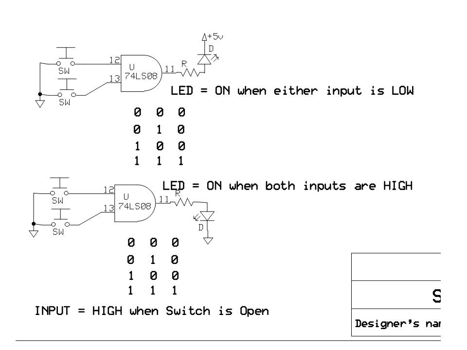
But during the testing phase I’ve encountered some problems. Wires are going from ground to a 4 dip-switch. From switch 1 to input 1, switch 2 to input 2(HD74LS08P = AND-gate) The output is connected to a led.
The table I’m getting is the same as a nand gate?! So when the switches are off the led is on.
With 74 series chips an open is high. But it's still standard-practice to use pull-up resistors.
I really don't think this clearly explains the issue.
The OP never applied logic HIGHs to the inputs of the AND gate.
"Floating never has been and never will be equivilent to HIGH. A High is a voltage that conforms to TTL spec for logic high, not a floating input.
Unconnected LS inputs will be read as High. That's why LS outputs have meager high output drive current (0.4mA), and good (relatively) low output current (8mA), to be able to drive pulled up inputs low.
Inputs only need 20uA (0.02mA) to go high, but 0.4mA is needed to take them low.
Wires are going from ground to a 4 dip-switch. From switch 1 to input 1, switch 2 to input 2(HD74LS08P = AND-gate) The output is connected to a led.
The table I'm getting is the same as a nand gate?!
The OP is applying LOGIC LOWs NOT logic HIGHs. There are no floating inputs
(The inputs are connected to GND via the switches)
The OP asked "What am I doing wrong", to which the answer is
"Your dip switch is connected to GND instead of 5V."
Beats me why you would buy, let alone propose to use, ICs that are completely obsolete!
Logic is logic.
The USNAVY Is still using four file cabinets full of vacuum tubes that comprise 2 FLIP FLOPS in the Bremerton Naval Shipyard in Washington. I saw them with my own eyes.
I don't see how any of you can have confidence in what is going on over in OP land. We can only assume the OP has any of this connected properly. And when he/she says, "output is connected to a led", connected how?
To the OP [Original Poster -- i.e. "PepijnK"]: We need a schematic of your set up, or at least a decent photo that makes it possible to see what you're doing.
DVDdoug:
So when the switches are "on" you have logic-low and when the switches are off you have "logic high".
With 74 series chips an open is high. But it's still standard-practice to use pull-up resistors.
No, 74LS series require 10k pullups on any high input, and inputs should not be wired to
5V directly. Low inputs can be strapped to 0V.
But first why 74LS family? They are decades old and obsolete in modern design. The 74HC series
is the go-to general purpose logic family these days, and are CMOS, not TTL. 74HC inputs can be directly
connected to the 5V rail. Still will need pullups or pulldowns for switch inputs, but the resistor value is not
very critical.
74HC series are more flexible, can be powered from 2 to 6V. 74LS must have a 5.0V supply.