7seg display blinks

Hello everyone, I hope for your great minds and responsiveness.

So, the background: The idea came to my wife for a present - a frame that shows how many years, months and days we are together, and on the same board there is a second counter that shows how many days are in total together. In theory, everything is simple, the clock on the DS1307 and the difference in dates are displayed on the 7-segment display.

Links to the video of the finished device:

  1. Video 1

  2. Video 2

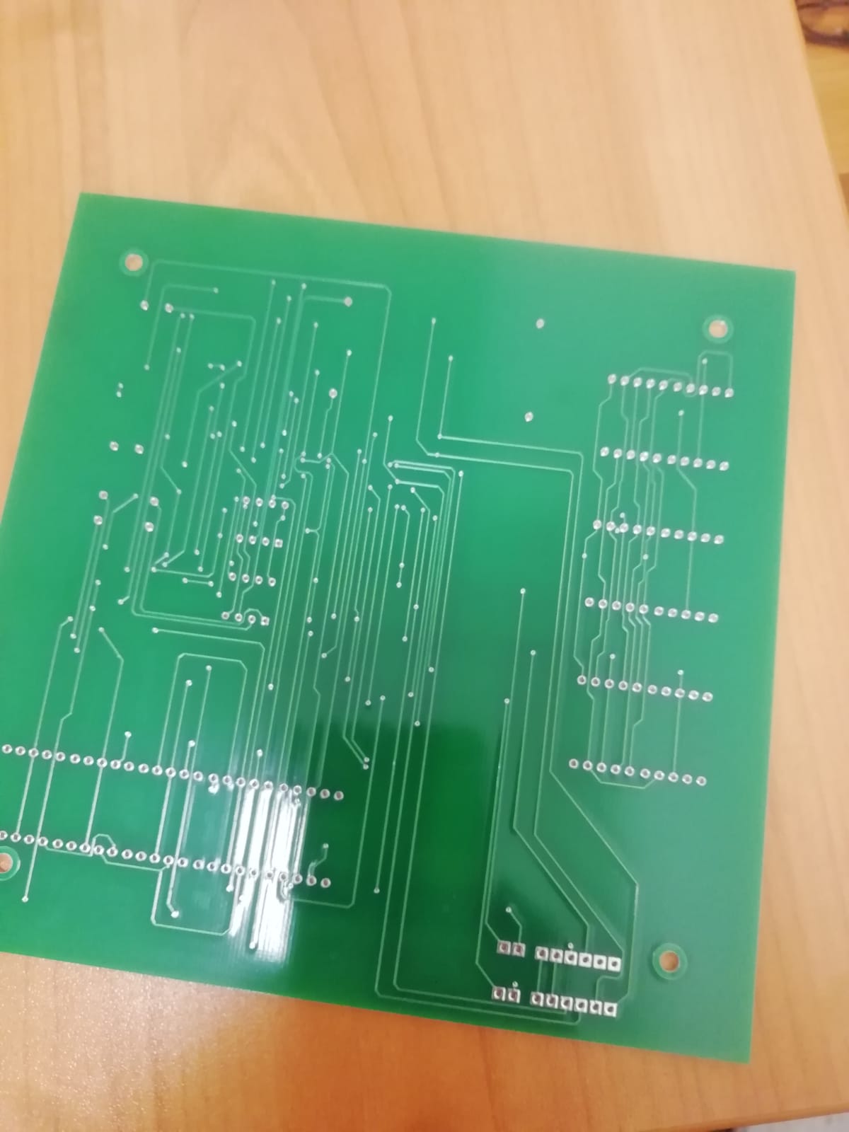
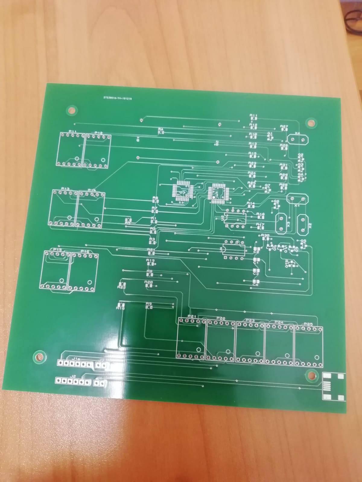
I ordered the boards, printed the case, and then the weak point = firmware. Here I copied everything from any examples, tried to figure it out and combine everything into one, and with my knowledge that was equal to zero, I realized what I had conceived, but with one problem it was a visible switching between indicators, that is, changing the delay values at the end of the code I clearly see how fast or slower they switch. If I set the value already in delayMicroseconds starts to fade the display and only one digit shines clearly.

I collected everything in a proteus, there I tested it in a simulation.

It turns out indicators with a common anode, all on transistors.

#include <Wire.h>    //Libraries to communicate with RTC
#include "RTClib.h"

RTC_DS1307 rtc;      //create rtc object

int segs[] = {0, 1, 2, 3, 4, 5, 6, 7}; //abcdefg. segments
int digits[] = {12, 13, 10, 11, 8, 9}; //number of digits

byte num[]  = { B11000000, B11111001, B10100100, B10110000, B10011001, B10010010, B10000010, B11111000, B10000000, B10010000 };
int t, dm, Y, M ,D;

DateTime dob = DateTime(2010, 6, 27, 0, 0, 0);
int t0 = dob.year() * 12 + dob.month() - 1;

void setup()
{
  rtc.begin(); //begin rtc communication
  //rtc.adjust(DateTime(2019, 12, 23, 20, 04, 0));


  for (int i = 0; i < 8; i++)
  {
    pinMode(segs[i], OUTPUT);//set segment pins output
  }
  for (int i = 0; i < 6; i++)
  {
    pinMode(digits[i], OUTPUT);//set digts as outputs
  }
}

void loop()
{
  DateTime now = rtc.now();
  t = now.year() * 12 + now.month() - 1;
  dm = t - t0;

  if (now.day() >= dob.day()) {
    Y = floor(dm / 12);
    M = dm % 12;
    D = now.day() - dob.day();
  } else {
    dm--;
    t--;
    Y = floor(dm / 12);
    M = dm % 12;
    DateTime tmp = DateTime(floor(t / 12), (t % 12) + 1, dob.day(), 0, 0, 0);
    D = (now.unixtime() - tmp.unixtime()) / 60 / 60 / 24;
  }
  
  printTime(D, M, Y);
}
void printNum(int number) //function to print number
{
  byte data = num[number];
  for (int i = 0; i < 8; i++)
  {
    if (data & 0x01)
      digitalWrite(segs[i], HIGH);
    else
      digitalWrite(segs[i], LOW);
    data >>= 1;
  }
}

void printTime(int D, int M, int Y)
{
  int d[] = { floor(D / 10), D - 10 * floor(D / 10), floor(M / 10), M - 10 * floor(M / 10), floor(Y / 10), Y - 10 * floor(Y / 10) };

  for (int i = 0; i < 6; i++)
  {
    if (i == 0) digitalWrite(digits[5], LOW);
    if (i != 0) digitalWrite(digits[i - 1], LOW);
    digitalWrite(digits[i], HIGH);
    printNum(d[i]);
    delay(1);
  }
}

The idea looks nice. Looks like you can be together for up to 99 years.

However, the transistors look a bit out of place.

You've said the displays are common anode so I would have expected to see PNP transistors switching on the high side.

Since you are multiplexing the displays so only one display is on at any one time, then there can be no big delays. Usually , it is better to use a timer for the switching (say at 4mS intervals) and the complex date/time calculations should be done in the loop.

6v6gt:
The idea looks nice. Looks like you can be together for up to 99 years.

However, the transistors look a bit out of place.

You've said the displays are common anode so I would have expected to see PNP transistors switching on the high side.

Since you are multiplexing the displays so only one display is on at any one time, then there can be no big delays. Usually , it is better to use a timer for the switching (say at 4mS intervals) and the complex date/time calculations should be done in the loop.

Unfortunately, I'm beginner, it will take a lot of time from understanding to realizing, but thank you very much, hope I will fix my code until 14th February. :slight_smile:

Looking at the PCB and the video, it does appear that the schematic shows only one part of your project.
Have you the schematic also for the total days counter ?
Have you a link to the data sheet for the displays ?

Since it appears to work (but with unwanted blinking), I assume that there is a mismatch between the schematic and the circuit. It won't be that difficult to fix if the display is showing the correct information, that is 9 years, 5 months and 27 days.

Because you have used pin 1 (TX) for the display, you can't use the serial monitor to debug the sketch. You did know that you could have used the remaining analog pins in the range A0 to A5 (ie not A6 and A7) as normal digital pins ?

I would also suggest that you replace the DS1307 and use a DS3231 since this is supposed to be a long-running project. the DS1307 can drift by minutes per month which will eventually be noticeable. The DS3231 is something like a few seconds per year.

Or make sure you build in an adjustment feature.

I've modified your script so the display handling is done in a timer routine and is not, therefore, affected by the heavy calculations in the loop. This should eliminate flicker.
I made minimal changes so the script structure stays the same but there is still some scope for optimisation.
I haven't tested it, but it compiles (with a few warnings as before).

#include <Wire.h>    //Libraries to communicate with RTC
#include "RTClib.h"
#include <TimerOne.h>

RTC_DS1307 rtc;      //create rtc object

int segs[] = {0, 1, 2, 3, 4, 5, 6, 7}; //abcdefg. segments
int digits[] = {12, 13, 10, 11, 8, 9}; //number of digits

volatile int display[ 6 ] = { 0 } ;   // global display buffer

byte num[]  = { B11000000, B11111001, B10100100, B10110000, B10011001, B10010010, B10000010, B11111000, B10000000, B10010000 };
int t, dm, Y, M , D;

DateTime dob = DateTime(2010, 6, 27, 0, 0, 0);
int t0 = dob.year() * 12 + dob.month() - 1;

void setup()
{
  rtc.begin(); //begin rtc communication
  //rtc.adjust(DateTime(2019, 12, 23, 20, 04, 0));


  for (int i = 0; i < 8; i++)
  {
    pinMode(segs[i], OUTPUT);//set segment pins output
  }
  for (int i = 0; i < 6; i++)
  {
    pinMode(digits[i], OUTPUT);//set digts as outputs
  }

  Timer1.initialize(4000);   // timer period in uS - adjust this affects  flicker / brightness
  Timer1.attachInterrupt( printTime ); // printTime() now called by timer interrupt

}


void loop()
{
  DateTime now = rtc.now();
  t = now.year() * 12 + now.month() - 1;
  dm = t - t0;

  if (now.day() >= dob.day()) {
    Y = floor(dm / 12);
    M = dm % 12;
    D = now.day() - dob.day();
  } else {
    dm--;
    t--;
    Y = floor(dm / 12);
    M = dm % 12;
    DateTime tmp = DateTime(floor(t / 12), (t % 12) + 1, dob.day(), 0, 0, 0);
    D = (now.unixtime() - tmp.unixtime()) / 60 / 60 / 24;
  }

  // printTime(D, M, Y);
  int d[] = { floor(D / 10), D - 10 * floor(D / 10), floor(M / 10), M - 10 * floor(M / 10), floor(Y / 10), Y - 10 * floor(Y / 10) };

  noInterrupts() ;
  // disable interrupts to stop possible conflict with timer call back routine and load global display buffer
  for (int i = 0; i < 6; i++) display[ i ] = d[ i ] ;
  interrupts() ;

  delay( 1000 ) ; // not nice
}


void printNum(int number) //function to print number
{
  byte data = num[number];
  for (int i = 0; i < 8; i++)
  {
    if (data & 0x01)
      digitalWrite(segs[i], HIGH);
    else
      digitalWrite(segs[i], LOW);
    data >>= 1;
  }
}


void printTime()
{
  // printTime() called from timer call back routine
  // displays the next digit when called.
  
  static int i = 0 ;  // note that a static variable is initialised only once !

  if (i == 0) digitalWrite(digits[5], LOW);
  if (i != 0) digitalWrite(digits[i - 1], LOW);
  printNum( display[ i ]); // write segments before anode is switched on
  digitalWrite(digits[i], HIGH);
  i++ ;  // set up i for the next call
  if ( i > 5 ) i = 0 ;
}

6v6gt:
You've said the displays are common anode so I would have expected to see PNP transistors switching on the high side.

If the displays are common anode, then you will have transistors in the cathode circuits of each segment, this is low side switching and you use NPN transistors.
Tom... :slight_smile:

TomGeorge:
If the displays are common anode, then you will have transistors in the cathode circuits of each segment, this is low side switching and you use NPN transistors.
Tom... :slight_smile:

Well, I could have written some rubbish. It does happen from time to time, but not often. You did see that the displays are being multiplexed ?

The OP didn't say what common anode display elements he is using, but let's assume he is using these: LN5101BS2B

He has put all the cathodes in parallel and is multiplexing the displays.
Let's say he is driving these so each segment can run at 10mA via the current limiting resistor.
At any one time, only the wanted segments for a specific digit will be lit.
An Arduino pin can well sink the 10 mA each for the lit segment so no low side transistor is required. However, if the display is showing an '8' that is 70mA in total for the currently displayed digit, so an Arduino pin cannot source it, so the common anode has to be switched with a transistor. It is being switched on the high side, hence the preference for a PNP transistor.

What is clear is that the OP's schematic is incorrectly drawn and could cause confusion.