Not completely sure but think this is right section for this type of question to ask.
I just want to ask if my 800W resistive load bank can be improved any further(besides fan control) before I will start switching to pcb design.
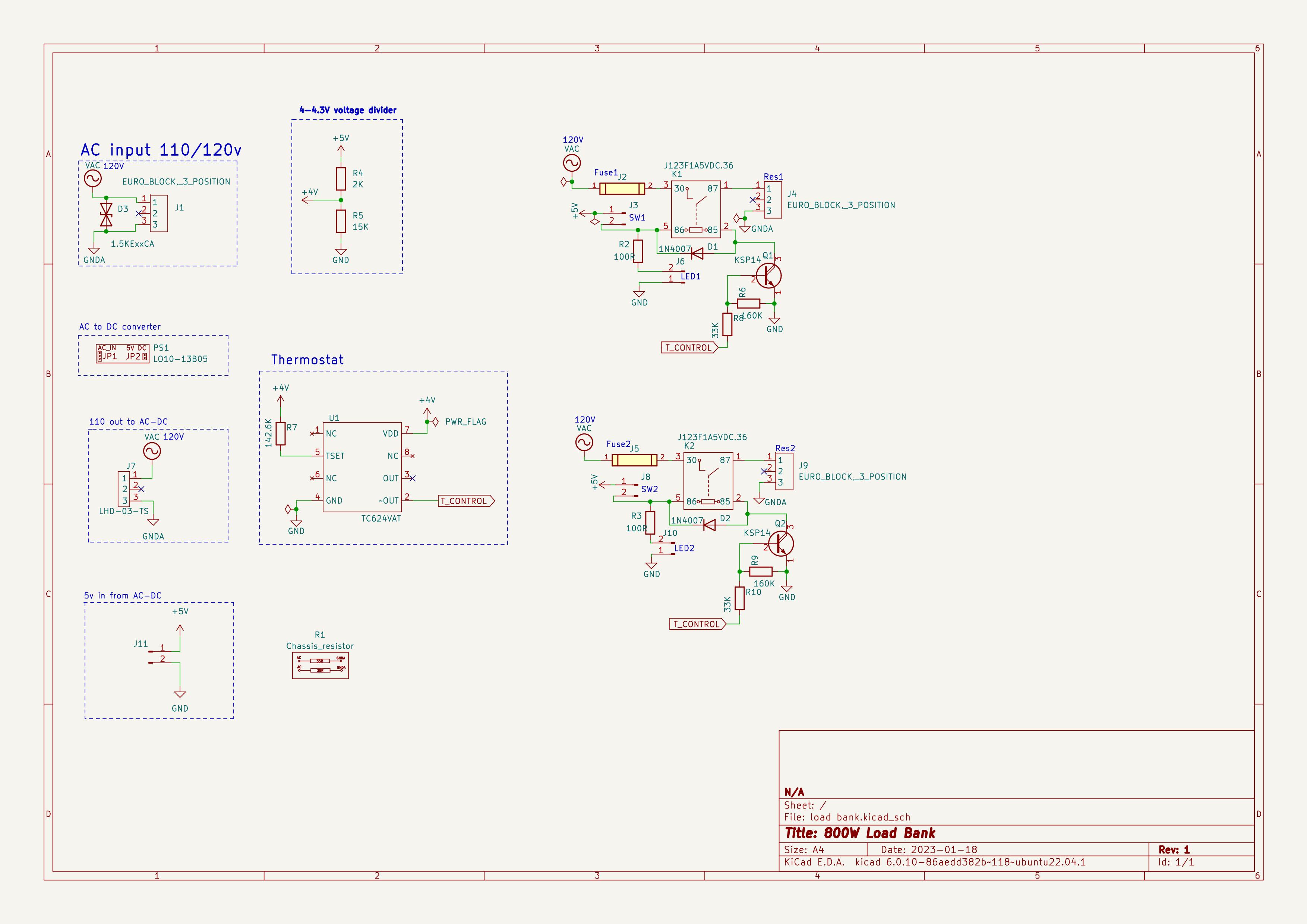
Its temperature controlled double 400W resistive load. I choose KSP14 darlingtons to boost 250ua output from TC624 ic via 33K resistors connected in parallel to drive 500w 71Ohm relay coils.
Overvoltage,overcurrect protection done in 110v-5V regulator and on 110V lines going to relay contacts too via 4A fuses.
Added 15KE series 128V tvs diode by vishay too for spikes right on 110 input line break down starts at around 150 and full clamp at 200V this was the best value I could find.
Each 35Ohm resistor is huge 27cm from Ohmite.
Fans ans enclosure still in process.
I suspect General Electronics would be a better place, do you want me to move this?
I can't follow your schematic because it is 'join the dots' where I have to imagine what is connected to what. Also, are there other pages not shown? For example what is really in the block marked 'AC to DC converter'?
I'm guessing this is a load intended for 120VAC, although if you said that I missed it.
I don't see any load resistors on your schematic. Saying they are 'huge' is meaningless, providing a link to them and stating their rated power output and maximum voltage would be helpful.
(OK, I think I found them, would they be the 2 resistors marked ' R1 chassis resistor'? One resistor or 2? Confusing)
You appear to be trying to power your temperature sensor from a resistive divider, you can't do that. Resistive dividers are for reference voltages where you take no meaningful amount of current from them. As soon as you draw any current the voltage will change. (I thought at first it was being used as a reference for the set point, but now I think it's meant for power. Perfect example of why you should not use 'join the dots' schematics.)
For switching relays use a MOSFET, much better than a bipolar transistor, and no need to worry about how much current the gate takes.
Just a comment as a mod:
Please keep any questions about your PCB in this topic rather than a new one because the work on your circuit design is useful background to any comments about the PCB design).
Hi, @surepic
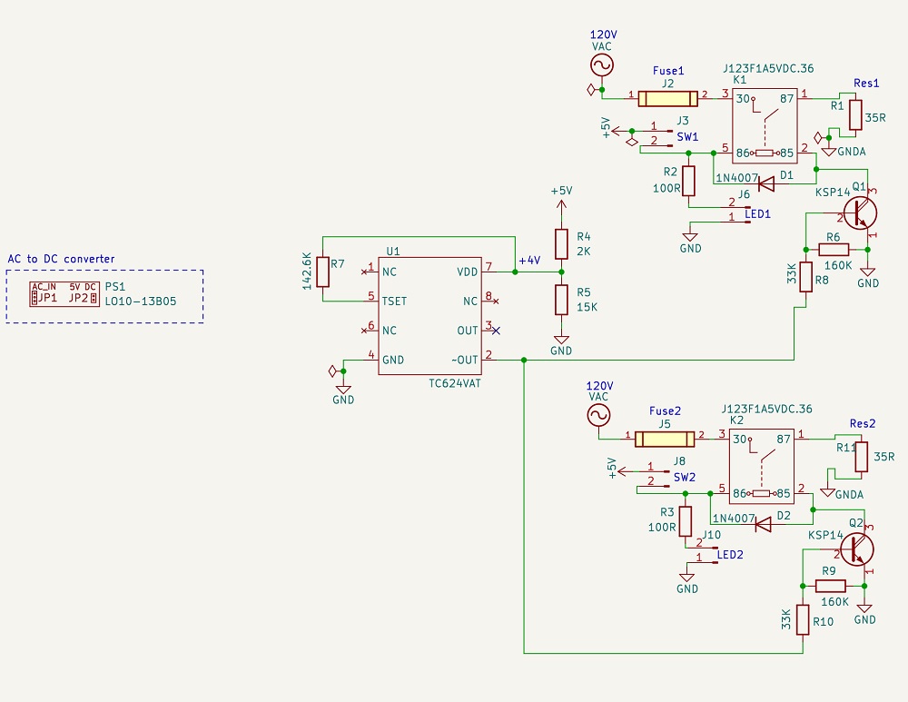
Your schematic in net name form is okay for PCB design, however it becomes a "search a word" when it come to circuit analysis.
Your schematic is well labeled and clean in layout. ![]()
![]()
Can you provide a layed out schematic with all connections made, it is okay to use gnd and 120Vac net names but easier to follow if you connect the rest of the nets with wires.
Please include ALL components, even the ones that are connected to for example J4 and J9.
Thanks.. Tom.. ![]()
![]()
![]()
![]()
PS. There are schematics for PCB layout and schematics for troubleshooting and circuit checking.
Thanks for input guys. As Tom said its easier to switch to pcb design with net names.
For voltage divider output to ic i thought of negligible current of 300ua of IC and supply voltage of 4-4.3v resistive divider should do the job considering stable output from ac dc converter. Please confirm that resistive divider wont work in my case as intended.
I didnt want to flood with all parts listed and datasheets but i will today that defines will help understand schematic. And will wire all components instead of net names for ease of troubleshooting.
Capacitors in the schematic i will add after will approximate needed airflow for dc fan selection.
Thanks again !

Schematic in the first post updated by wiring everything instead of net names.
Confusing jumpers and dotted lines deleted.
Parts used in the schematic with datasheets:
LO10-13B05 AC-DC converter 2A 5V
https://www.mornsun-power.com/html/pdf/LO10-13B05.html
U1 TC624 Thermostat
https://ww1.microchip.com/downloads/en/DeviceDoc/21440D.pdf
K1 and K2 5vdc 120v 500W relay J123f1a5vdc.36 https://www.citrelay.com/Catalog%20Pages/RelayCatalog/J123F.pdf
Q1 and Q2 KSP14 darlington NPN https://www.onsemi.com/download/data-sheet/pdf/ksp13-d.pdf
R1 and R11 load resistors C500K35RE https://www.ohmite.com/assets/docs/res_280.pdf
All other parts are standard resistors,connectors and switches.
I've had a look at the data sheet. This is one of those cases where I think you should not do it like that but no harm in experimenting. You certainly need a capacitor on the power input if you are doing that, maybe 10μF. I'm not going to confirm it will or won't work, but will be interested to know what you find out by trying. The more usual way to do it like that would be a Zener diode of the appropriate voltage and a resistor that can supply maybe 10 x the required current. However, looking at the data sheet I see that there are many version of that chip that will work on 5V, so I wonder why you didn't choose one of those.
I would hope that when you post a new schematic it will include MOSFETs to drive the relay coils. I'm not going to suggest which one, but don't forget it needs to be logic level.
Can I trouble you to revert to the previous version please? Then post the new schematic in a new post. By editing the original post you've just made mine and Tom's replies look daft.
Fixed. ![]()
I double checked all available versions of TC624 and they work in range 2.7-4.5VDC.
Difference between TC622 and 624 is that the first one needs thermistor the second one doesnt.
Hi, @surepic
Thanks for the schematic, but don't go back and edit, just put your changes in new posts, that way the flow of the thread will not be confusing to anyone looking at it later.
Have you breadboarded the 624 to check if it is happy with potential divider power supply?
Might I also suggest some bypass capacitors in your circuit so relay noise does not get into the temperature sensor.
Specifically 0.1uF caps on the 624 Vdd terminal and the Tset terminals to gnd.
Tom.. ![]()
![]()
![]()
![]()
PS. I'm off to bed, its 1:18am here.. ![]()
![]()
![]()
![]()
![]()
OK, reason for TC624 understood. If you want to use a resistive divider you will have to experiment to find out if it works OK. I suspect you've be better off using a 3V3 LDO linear regulator an powering it from that. If you do insist on using a voltage divider then remember the current drawn will change when the output switches, so the supply voltage will change. Whether it matters is for you to find out.
If you will insist on using bipolar transistors there's no need for R6 and R9. If you use MOSFETs (hint) then keep one resistor from TC624 to 0V, that is, from the output pin to 0V. MOSFETs should be logic level and capable of being on at 3V3 or 4V (or whatever).
Can you clarify the reason for 2 relays? Are you wanting to be able to turn each 400W load on and off independently?
Do you understand that LED1 and LED2 will be lit whenever their respective switches, SW1 and SW2, are on, regardless of whether the relay is operated. Is this what you want?
Capacitors suggestion accepted and are in schematic didnt upload here yet.
For breadboard testing no I didnt even order TC624 to test in real. Will do when will finish schematic in full. Also PerryBebbington suggestion of using zener diode and resistor sounds appealing.
Another suggestion for the power: I see the TC624 can be powered at 4V5, a typical silicon diode drops about 0.6V to 0.7V, so just power from 5V with a diode in series to pin 7, Vdd. Capacitor still needed.
I`m not good at choosing and understanding in full FETS am always trying to use bjts its kinda phobia I guess ![]()
For 2 relays you got it right they must be controlled independantly.
For leds I was trying to put them after relay to kinda show if resistors are on or off but then was loosing voltage and current on BJT Ic.
I'm going to leave it to someone else to suggest a suitable MOSFET because I don't have one in mind and I am sure someone else will suggest one they've used before.
I think the diode voltage dropper I suggested in reply #13 is best.
If you want the LEDs to show the relay is on then disconnect the cathode (pointy end) from 0V (GND) and instead connect to pin 2 of the relay. 100 Ohm resistor probably too low, maybe 220 Ohms.
I am going to move this topic to general electronics, I think it's more appropriate there and likely to get more visibility.
Diode suggestion was simple and awesome.
For led its 30ma working current, i guess i have to find datasheet for the one i chose too.
I tried simulating led to pin 2 before via fastlad and i had no current flow due to 70ohm coil resistance vs 100ohm at led. Thats why scrapped that idea but didnt tested on breadboard tho!
Further thought on this: The load resistors are going to be on a great big fan cooled heat sink (I assume), so away from the PCB. It makes sense to use a temperature measuring device that has a remote sensor, not one that senses the temperature of the package. For this reason I suggest you forget the TC624 and use the TC622 with the thermistor, which can go remotely on the heat sink. Use twisted pair wire with heat proof insulation. Or change your design completely and use a DS18B20 with a micro-controller to monitor the temperature. A Nano with 2 off DS16B20, switches at inputs, LEDs and relay drivers at outputs will do everything you want. If you later wanted to add a display (for temperature?) or a timer maybe, such things would be easy.
Are you trying to blind yourself? For and indicator LED 30mA is way too much. Modern LEDs for indicators are fine with about 5mA or so.
I think you need to buy some components and start experimenting.
That's because the transistor cannot supply enough current, probably because the current into its base is not enough, probably because of the resistive divider power supply and the 33k base resistor.
Fans i was thinking suppose to be in serial. I.e. one on each end of rectangular enclosure that way i would be able to sense temperature of resistors because air flow will be thru the pcb. Will look further for using tc622.
I doubt it, they will be sensing the temperature of the air!
You know the load is 400W per resistor, you need enough cooling to make sure the heat sinks never get hot. You still need to protect against over heating because of, for example, fan failure.