8bit LCD Library

I have a 2 x 16 LCD screen with 16 pins. I included the LiquidCrystal Library and set up a test site and connected everything as suggested. It worked fine and displayed "Hello World" as expected.
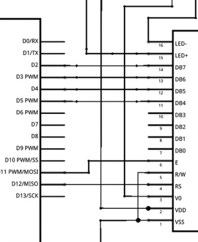
Then I tried to add it to my project, which unfortunately used the same pins as my working 433Mhz receiver, so I attempted to reassign pin 11 and pin 12 to pins 9 and 10 respectively, and move the data pins from 2 - 5 to pins 4 - 7. changed following lines to reflect the change.

const int rs = 10, en = 9, d4 = 7, d5 = 6, d6 = 5, d7 = 4;
LiquidCrystal lcd(rs, en, d4, d5, d6, d7);
as shown in example


This is part of the LiquieCrystal.cpp file Do I have to change anything in here to resolve this?
//
// Note, however, that resetting the Arduino doesn't reset the LCD, so we
// can't assume that its in that state when a sketch starts (and the
// LiquidCrystal constructor is called).

LiquidCrystal::LiquidCrystal(uint8_t rs, uint8_t rw, uint8_t enable,
uint8_t d0, uint8_t d1, uint8_t d2, uint8_t d3,
uint8_t d4, uint8_t d5, uint8_t d6, uint8_t d7)
{
init(0, rs, rw, enable, d0, d1, d2, d3, d4, d5, d6, d7);
}

LiquidCrystal::LiquidCrystal(uint8_t rs, uint8_t enable,
uint8_t d0, uint8_t d1, uint8_t d2, uint8_t d3,
uint8_t d4, uint8_t d5, uint8_t d6, uint8_t d7)
{
init(0, rs, 255, enable, d0, d1, d2, d3, d4, d5, d6, d7);
}

LiquidCrystal::LiquidCrystal(uint8_t rs, uint8_t rw, uint8_t enable,
uint8_t d0, uint8_t d1, uint8_t d2, uint8_t d3)
{
init(1, rs, rw, enable, d0, d1, d2, d3, 0, 0, 0, 0);
}

LiquidCrystal::LiquidCrystal(uint8_t rs, uint8_t enable,
uint8_t d0, uint8_t d1, uint8_t d2, uint8_t d3)
{
init(1, rs, 255, enable, d0, d1, d2, d3, 0, 0, 0, 0);
}

void LiquidCrystal::init(uint8_t fourbitmode, uint8_t rs, uint8_t rw, uint8_t enable,
uint8_t d0, uint8_t d1, uint8_t d2, uint8_t d3,
uint8_t d4, uint8_t d5, uint8_t d6, uint8_t d7)
{
_rs_pin = rs;
_rw_pin = rw;
_enable_pin = enable;

_data_pins[0] = d0;
_data_pins[1] = d1;
_data_pins[2] = d2;
_data_pins[3] = d3;
_data_pins[4] = d4;
_data_pins[5] = d5;
_data_pins[6] = d6;
_data_pins[7] = d7;

if (fourbitmode)
_displayfunction = LCD_4BITMODE | LCD_1LINE | LCD_5x8DOTS;
else
_displayfunction = LCD_8BITMODE | LCD_1LINE | LCD_5x8DOTS;

begin(16, 1);
}

Sorry I can't help with the code, however the LCD's I have are I2C or SPI. I though there was an adapter board to provide the serial functions, however I can't recall exactly what it was. I'm not home so I can't look at my parts. Such an interface is much easier to program (at least for me).

This may be the interface, can't be sure with so little info.

Thanks JohnRob, I understand but this is what I have for the moment and just wonder if somehow the library determines what pins it "has" to use. VirtualWire requires 11 for receive and 12 for transmit as installed, I believe they can be changed, not sure, but I already have that working so I just wanted to use this lcd screen that I have for additional testing.

I understand, sorry I couldn't be of more help with the code.

What exactly is the problem you are having with the display? Is it not displaying anything now, displaying something incorrectly, etc? Do you get an error when compiling? I don't really see anything in your original post that states what is wrong.

Do not modify the .cpp file. There is no need to change any library files. Just change the LCD constructor in your code to reflect the pins that you are actually using like you show.

This constructor should work:

const int rs = 10, en = 9, d4 = 7, d5 = 6, d6 = 5, d7 = 4;
LiquidCrystal lcd(rs, en, d4, d5, d6, d7);

Have you tried adjusting the contrast pot?

I do not use any of the LiquidCrystal libraries. The best library for the hd44780 controlled character displays is the hd44780 library. It is available through the IDE library manager.

Here is a "Hello World" sketch using the HD44780 library.
Using your pin out. rs = 10, en = 9, db4 = 7, db5 = 6, db6 = 5, db7 = 4;
Tested and prints "Hello, World!" on line 0 and "millis = " and the current millis() on line 1.

#include <hd44780.h>
#include <hd44780ioClass/hd44780_pinIO.h> // Arduino pin i/o class header

const int rs = 10, en = 9, db4 = 7, db5 = 6, db6 = 5, db7 = 4; 
hd44780_pinIO lcd(rs, en, db4, db5, db6, db7);

const int LCD_COLS = 16;
const int LCD_ROWS = 2;

void setup()
{
   lcd.begin(LCD_COLS, LCD_ROWS);
   lcd.print("Hello, World!");
}

void loop()
{
   static unsigned long timer = 0;
   unsigned long interval = 1000;
   if (millis() - timer >= interval)
   {
      timer = millis();
      lcd.setCursor(0, 1);
      lcd.print("millis = ");
      lcd.print(millis());
   }
}

No LCD screen display is the problem, sorry I did not make that clear. I am going to see if groundFungus' sketch works. I had actually changed the constructor to what he provided with the LiquidCrystal library and it did not work, so off to the rodeo :slight_smile:

Works like a champ, couldn't figure out with the LiquidCrystal Library wouldn't accept this
const int rs = 10, en = 9, d4 = 7, d5 = 6, d6 = 5, d7 = 4;
LiquidCrystal lcd(rs, en, d4, d5, d6, d7);
but since this works, I am tickled. I am waiting for my OLED with I2C connectivity to arrive, but this allows me to create and see the results of the logic that will feed the display.
Thank you again.

Perhaps consider simplifying the project. Have you considered using the I2C interface for the LCD? You can get LCDs with the module attached or buy the module separately
Then you need just the two I2C wires.
The library to use is LiquidCrystal_I2C

One small point. Many 433 rf modules are 3.3V, and many LCDs are 5v. You are not running into any issue there are you?

This topic was automatically closed 120 days after the last reply. New replies are no longer allowed.