8x8 LED Matrix common cathode row

Hi,

I'm using Arduino UNO on 0022 software...

I've wired up a single colour 8x8 LED Matrix common cathode row as per Project 17 of the Earthshine Electronics's Complete Beginner's Guide to Arduino ...

  • 1 8x8 led matrix
  • 2 74595 shift registers connected to each other ( pin 9 - 14 )
  • 8 220R ohm resistors

http://www.earthshineelectronics.com/files/ASKManualRev5.pdf

I could not get the multiplexing to work... all the LEDs just light up and flicker very fast...

Is it because my LED Matrix is common cathode rows whereas in the examples are common anode rows... ?

How to modify the codes to support common cathode rows LED Matrix ?

How come in the examples above, the LED Matrix / 74595 still works even when I did not ground/sink current of the shift registers ??

I've google for solutions but most seems to be using a different method of doing multiplexing...

My goals was to scroll text across the LED Matrix ...

Thanks in advance

I've wired up two 74595 shift registers to the following :-

1st shift registers ( common cathode rows ) :-

A - 9
B - 14
C - 8
D - 12
E - 1
F - 7
G - 2
H - 5

2nd shift registers ( common anode columns ) :-

A - 13
B - 3
C - 4
D - 10 
E - 6
F - 11
G - 15
H - 16

I tried lighting up the rows & columns using shiftOut and it seems to be working fine using the code below :-

int latchPin = 12; //74595 connected to LatchPin, 12 on 74595
int clockPin = 11; //Shared clockPin, 11 on 74595
int dataPin = 10; //Shared dataPin, 14 on 74595

byte data;

byte dataArray[8]; //Array to set the leds

void setup() {
  Serial.begin(9600);

  pinMode(latchPin, OUTPUT);
  pinMode(clockPin, OUTPUT);
  pinMode(dataPin, OUTPUT);
  Serial.println("Ready");

  dataArray[0] = 1;
  dataArray[1] = 2;
  dataArray[2] = 4;
  dataArray[3] = 8;
  dataArray[4] = 16;
  dataArray[5] = 32;
  dataArray[6] = 64;
  dataArray[7] = 128;
  
}


void loop() {

  // Display rows (push 2 bytes into 74595)
  for(int i = 0; i < 8; i++)  {
    data = ~dataArray[i];
    digitalWrite(latchPin, LOW);
    Serial.println(data, BIN);
  
    shiftOut(dataPin, clockPin, MSBFIRST, B11111111);
    shiftOut(dataPin, clockPin, MSBFIRST, data );
    digitalWrite(latchPin, HIGH);
    delay(100);
  }

    // Display columns  (push 2 bytes into 74595)
    for(int i = 0; i < 8; i++)  {
    data2 = dataArray[i];
    digitalWrite(latchPin, LOW);
    Serial.println(data2, BIN);
 
    shiftOut(dataPin, clockPin, MSBFIRST, data2);
    shiftOut(dataPin, clockPin, MSBFIRST, 0);
    digitalWrite(latchPin, HIGH);
    delay(100);
    }
}

LED Matrix.jpg

Is it because my LED Matrix is common cathode rows whereas in the examples are common anode rows... ?

Yes, it is not only the code you have to wire it up differently.
Post the schematic of what you have (that thing you posted is not a schematic it is a physical wiring diagram and is useless in determining if your design is right).

I got it working controlling the 8x8 LED Matrix by dots or rows... taking one step at a time b4 moving to do multiplexing...

Found out to sink the current of 74595, make it a zero to complete the LED circuit...

I've moved all the 220 Ohm resistors to the columns...

// LED Matrix is common cathode row

// Turn rows to 0 to sink current, turn row to 1, nothing will happen
// Turn columns to 1 to source current per columns
// 

// Follow SPI pinout
int latchPin = 10; //74595 connected to LatchPin, 12 on 74595
int clockPin = 13; //Shared clockPin, 11 on 74595
int dataPin = 11; //Shared dataPin, 14 on 74595

int array1[]= { 1,2,4,8,16,32,64,128,255 };
int array2[]= { 1,3,7,15,31,63,127,255 };

void setup() {
  // Serial.begin(9600);
  // Serial.println("Ready");

  pinMode(latchPin, OUTPUT);
  pinMode(clockPin, OUTPUT);
  pinMode(dataPin, OUTPUT);

  }


void blink_all() {

      for ( int i = 0; i < 8; i++) {
      digitalWrite(latchPin, LOW);
      shiftOut(dataPin, clockPin, LSBFIRST, B11111111);  // Columns, 1 to turn ON
      shiftOut(dataPin, clockPin, MSBFIRST, B00000000 ); // Rows, 0 to turn ON
      digitalWrite(latchPin, HIGH);
      delay(100);
      clear_all();
      delay(100);
      }
}

void clear_all() {
      digitalWrite(latchPin, LOW);
      shiftOut(dataPin, clockPin, MSBFIRST, 0 );  // Columns, 1 to turn ON
      shiftOut(dataPin, clockPin, MSBFIRST, 0 );  // Rows, 0 to turn 
      digitalWrite(latchPin, HIGH);
}

void row_by_row() {
     int row = 0;
     for ( int i = 0; i < 8; i++) {
      row = ~array1[i];  // invert the bits
      digitalWrite(latchPin, LOW);
      shiftOut(dataPin, clockPin, LSBFIRST, B11111111);  // Columns, 1 to turn ON
      shiftOut(dataPin, clockPin, MSBFIRST, row); // Rows, 0 to turn ON
      digitalWrite(latchPin, HIGH);
      delay(100);
      clear_all();
  }
}

void col_by_col() {
   int col = 0;
     for ( int i = 0; i < 8; i++) {
      col = array1[i]; 
      digitalWrite(latchPin, LOW);
      shiftOut(dataPin, clockPin, MSBFIRST, col);  // Columns, 1 to turn ON
      shiftOut(dataPin, clockPin, MSBFIRST, B0);   // Rows, 0 to turn ON
      digitalWrite(latchPin, HIGH);
      delay(100);
      clear_all();
  }
}

void one_by_one() {
 
  int row, col = 0;
  
// 2 loops of 8, 64 times
 for  (int i = 0; i < 8; i++) {
   for (int j = 0; j < 8; j++ ) {
      row = ~array1[i];  // invert the bits
      col = array1[j];
      digitalWrite(latchPin, LOW);
      shiftOut(dataPin, clockPin, MSBFIRST, col);  // Columns, 1 to turn ON
      shiftOut(dataPin, clockPin, MSBFIRST, row); // Rows, 0 to turn ON
      digitalWrite(latchPin, HIGH);
      delay(50);
      clear_all();
     
     } // j loop
  }  // i loop
  
}


void led_random() {

  for ( int i = 0; i < 50; i++) {
      digitalWrite(latchPin, LOW);
      shiftOut(dataPin, clockPin, MSBFIRST, array1[random(8)]);  // Columns, 1 to turn ON
      shiftOut(dataPin, clockPin, MSBFIRST, ~array1[random(8)]);  // Rows, 0 to turn ON
      digitalWrite(latchPin, HIGH);
      delay(100);
      clear_all();
  }
}

void loop() {

   blink_all();
   delay(500); 
   row_by_row();
   delay(500);
   col_by_col();
   delay(500);
   led_random();
   delay(500);
   one_by_one();
   delay(500);

} // end loop()

Made a simple alphabets scrolling text using ideas and fonts from the following ppl below:-

Scrolling text ideas from hari ( http://www.arduino.cc/cgi-bin/yabb2/YaBB.pl?num=1267391793/7 ) and A - Z bit patterns/fonts from aspro648 ( http://www.arduino.cc/cgi-bin/yabb2/YaBB.pl?num=1203747843/22 )

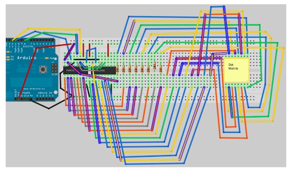
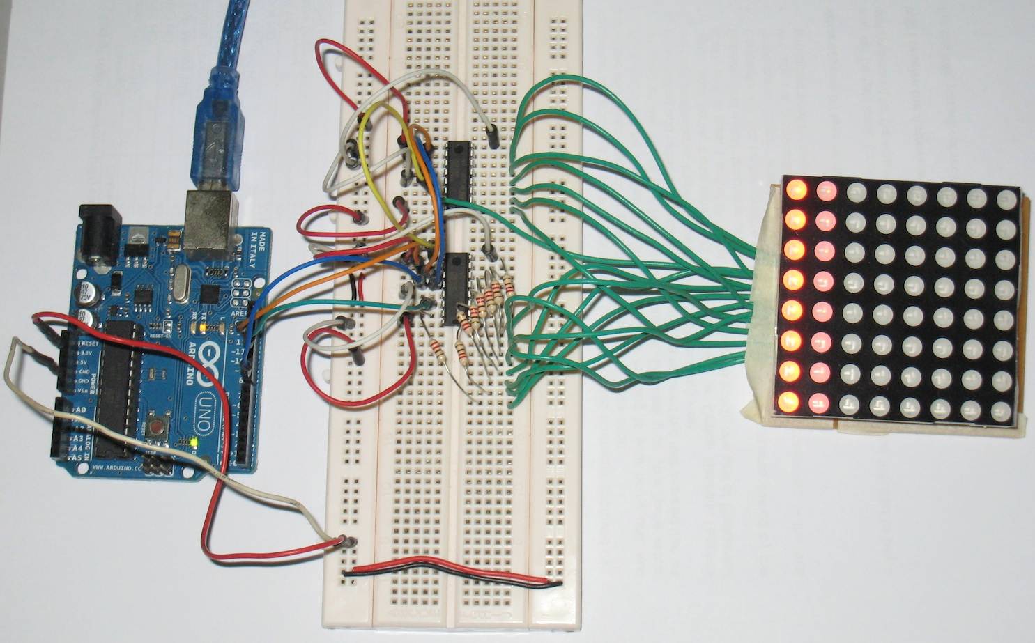
Their setup was for common anode row whereas my LED Matrix is common cathode row.

I just swap the shiftOut lines and change the MSBFIRST to LSBFIRST to suit the common cathode

       shiftOut(dataPin, clockPin, MSBFIRST, col);    // column, scan 0 to 7 by shifting 1 bit at a time
       shiftOut(dataPin, clockPin, LSBFIRST, ~buff);  // Use LSB to swap the char, made for CA

Stanley

Full sktech :-

// Red 8x8 LED Matrix for common cathode row
//
// Youtube video : http://www.youtube.com/watch?v=UaMYlHw4rek
// Blog : http://arduino-for-beginners.blogspot.com/
// 
//
// Turn rows to 0 to sink current, turn row to 1, nothing will happen
// Turn columns to 1 to source current per columns
// 
// 8 x 220 ohm resistors connected to A-G pins on 75595 shift registers 
// for common cathode rows

// Follow SPI pinout
int latchPin = 10; //  LatchPin, 12 on 74595
int clockPin = 13; //  clockPin, 11 on 74595
int dataPin = 11; //   dataPin, 14 on 74595

int array1[]= { 1,2,4,8,16,32,64,128,255 };
int array2[]= { 1,3,7,15,31,63,127,255 };

// font by aspro648 ( http://www.arduino.cc/cgi-bin/yabb2/YaBB.pl?num=1203747843/22 )
// First char is @, next is A, B, etc.  Only lower case, no symbols.  
// The @ will display as space character.

byte alphabets[][8] = {
  {
    0,0,0,0,0  }
  ,
  {
    31, 36, 68, 36, 31  }
  ,
  {
    127, 73, 73, 73, 54  }
  ,
  {
    62, 65, 65, 65, 34  }
  ,
  {
    127, 65, 65, 34, 28  }
  ,
  {
    127, 73, 73, 65, 65  }
  ,
  {
    127, 72, 72, 72, 64  }
  ,
  {
    62, 65, 65, 69, 38  }
  ,
  {
    127, 8, 8, 8, 127  }
  ,
  {
    0, 65, 127, 65, 0  }
  ,
  {
    2, 1, 1, 1, 126  }
  ,
  {
    127, 8, 20, 34, 65  }
  ,
  {
    127, 1, 1, 1, 1  }
  ,
  {
    127, 32, 16, 32, 127  }
  ,
  {
    127, 32, 16, 8, 127  }
  ,
  {
    62, 65, 65, 65, 62  }
  ,
  {
    127, 72, 72, 72, 48  }
  ,
  {
    62, 65, 69, 66, 61  }
  ,
  {
    127, 72, 76, 74, 49  }
  ,
  {
    50, 73, 73, 73, 38  }
  ,
  {
    64, 64, 127, 64, 64  }
  ,
  {
    126, 1, 1, 1, 126  }
  ,
  {
    124, 2, 1, 2, 124  }
  ,
  {
    126, 1, 6, 1, 126  }
  ,
  {
    99, 20, 8, 20, 99  }
  ,
  {
    96, 16, 15, 16, 96  }
  ,
  {
    67, 69, 73, 81, 97  }
  ,
};


void setup() {
   Serial.begin(9600);
   Serial.println("Ready...");

  pinMode(latchPin, OUTPUT);
  pinMode(clockPin, OUTPUT);
  pinMode(dataPin, OUTPUT);

  }

void clear_all() {
      digitalWrite(latchPin, LOW);
      shiftOut(dataPin, clockPin, MSBFIRST, 0 );  // Columns, 1 to turn ON
      shiftOut(dataPin, clockPin, MSBFIRST, 0 );  // Rows, 0 to turn 
      digitalWrite(latchPin, HIGH);
}

void blink_all() {

      for ( int i = 0; i < 8; i++) {
      digitalWrite(latchPin, LOW);
      shiftOut(dataPin, clockPin, LSBFIRST, B11111111);  // Columns, 1 to turn ON
      shiftOut(dataPin, clockPin, MSBFIRST, B00000000 ); // Rows, 0 to turn ON
      digitalWrite(latchPin, HIGH);
      delay(100);
      clear_all();
      delay(100);
      }
}

void row_by_row() {
     int row = 0;
     for ( int i = 0; i < 8; i++) {
      row = ~array1[i]; 
      digitalWrite(latchPin, LOW);
      shiftOut(dataPin, clockPin, LSBFIRST, B11111111);  // Columns, 1 to turn ON
      shiftOut(dataPin, clockPin, MSBFIRST, row); // Rows, 0 to turn ON
      digitalWrite(latchPin, HIGH);
      delay(100);
      clear_all();
  }
}

void col_by_col() {
   int col = 0;
     for ( int i = 0; i < 8; i++) {
      col = array1[i]; 
      digitalWrite(latchPin, LOW);
      shiftOut(dataPin, clockPin, MSBFIRST, col);  // Columns, 1 to turn ON
      shiftOut(dataPin, clockPin, MSBFIRST, B0); // Rows, 0 to turn ON
      digitalWrite(latchPin, HIGH);
      delay(100);
      clear_all();
  }
}

void one_by_one() {
 
  int row, col = 0;
  
// 2 loops of 8, 64 times
 for  (int i = 0; i < 8; i++) {
   for (int j = 0; j < 8; j++ ) {
      row = ~array1[i]; 
      col = array1[j];
      digitalWrite(latchPin, LOW);
      shiftOut(dataPin, clockPin, MSBFIRST, col);  // Columns, 1 to turn ON
      shiftOut(dataPin, clockPin, MSBFIRST, row); // Rows, 0 to turn ON
      digitalWrite(latchPin, HIGH);
      delay(50);
      clear_all();
     
   }
 }
  
}


void led_random() {

  for ( int i = 0; i < 50; i++) {
      digitalWrite(latchPin, LOW);
      shiftOut(dataPin, clockPin, MSBFIRST, array1[random(8)]);  // Columns, 1 to turn ON
      shiftOut(dataPin, clockPin, MSBFIRST, ~array1[random(8)]);  // Rows, 0 to turn ON
      digitalWrite(latchPin, HIGH);
      delay(100);
      clear_all();
  }
}

void char_loop() {
  
  byte buff;
 
   for (int x = 1; x < 27; x++) {
    for (int y = 0; y < 4; y++)  { 
     for (int j = 0; j < 10; j++) {      // Display the char 10 times quickly
      byte shift = B0000001;   
      if ( y > 0 ) { shift = shift << y; } // shift the column by y value
      for  (int i = 0; i < 8; i++) {

       byte col = shift;
       buff = alphabets[x][i];
   
       digitalWrite(latchPin, LOW);
       
       shiftOut(dataPin, clockPin, MSBFIRST, col);    // column, scan 0 to 7 using shift by 1 bit
       shiftOut(dataPin, clockPin, LSBFIRST, ~buff);  // Use LSB to swap the char, made for CA

       digitalWrite(latchPin, HIGH);
       delay(5);

       clear_all();
       shift = shift << 1; // Move to the next column
     } // i loop
    } // j loop
    delay(100);
   } // y loop
  } // x loop


}


void loop() {

   //blink_all();
   //delay(500); 
   
   //led_random();
   //delay(500);
   
   row_by_row();
   delay(500);
   
   col_by_col();
   delay(500);
            
   char_loop();
   delay(1000);

   led_random();
   delay(500);
   
   //one_by_one();
   //delay(500);

} // end loop()

I'm looking at one of the earlier versions for this, found at http://www.arduino.cc/cgi-bin/yabb2/YaBB.pl?num=1203747843/15 reply number 21 talks about using the cathode rows... I've switched my rows with my cols and I thought this should fix my problem, but now it scrolls backwards, and the letters are backwards as well, so that it is perfectly fine, only if viewed in a mirror... I can go in and change the order of the letters, but I cant figure out where in the code it is that controls the direction of the scrolling. Can anyone help with this?