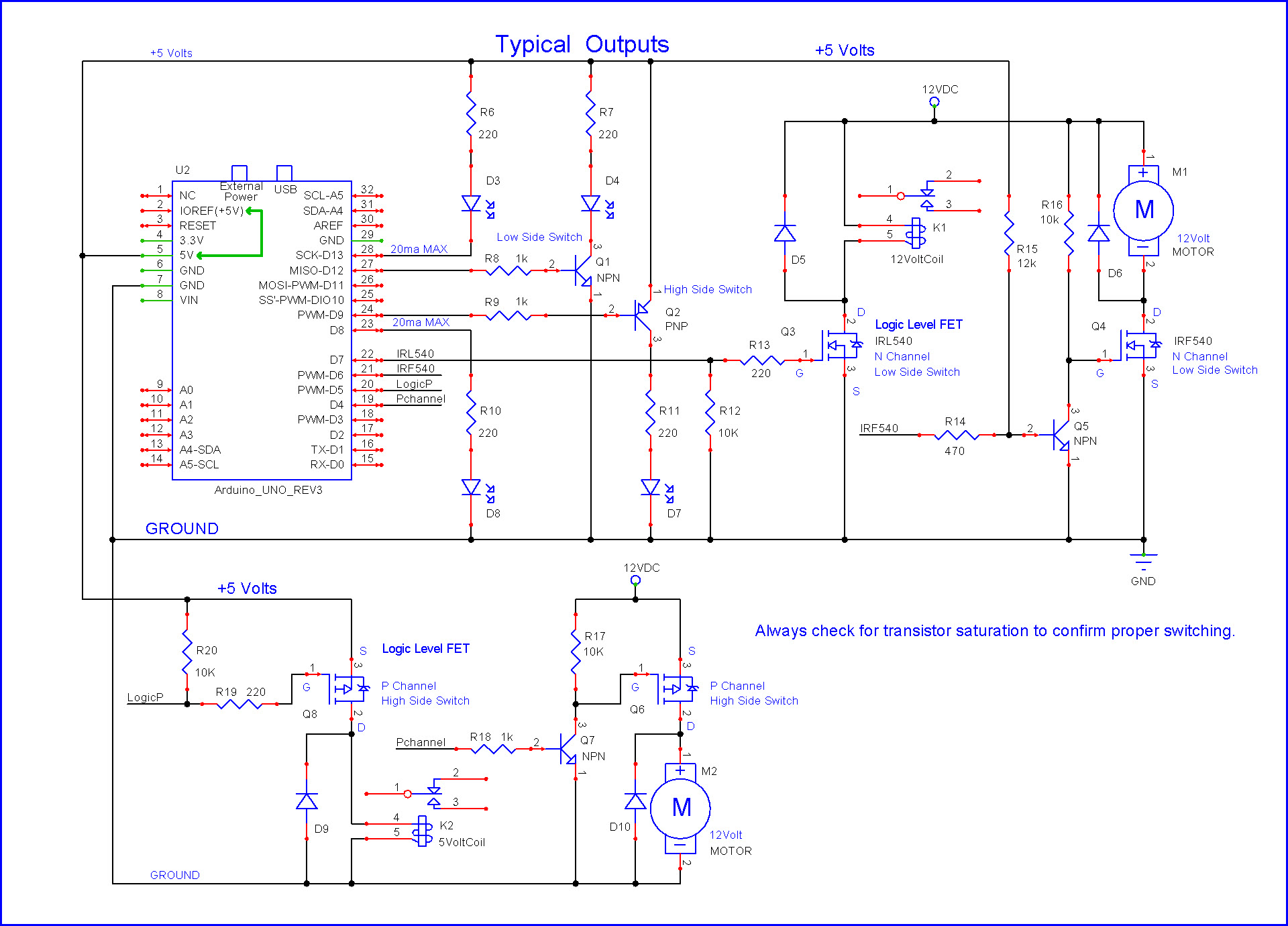
So I am great with the electronics, but crap with the programing. Attached is my schematic for a custom hat for an Arduino Nano to control an LED strip light. (Yeah, I know, another one of this projects.) However this one has a twist, I am planning on attaching it to an industrial button controller to act as the control station;
Green - Start a 1 hour program where the light slowly dims
Red - Turn off, I'm thinking this is just reset
Toggle up - Change program color
Toggle Down - Change starting brightness
E-stop - MONSTER MODE - Puts the light at full color and maybe 50% brightness in case kid gets scared.
I am happy to share any information including the PCB manufacturing files with anyone who is interested.
I am mostly looking for help with the programming.
I am using LED ribbon and am going to be knocking down the MOSFETs anyway as the loads are going to be pretty small. I'll look at the IRL520, but I think I'll be moving to a completely different package at this point, is only about 1.5m of LED. I'm starting some quick prototyping soon so I don't waste to much money on bad boards....
I have 5v going to buttons.
I just can't wrap my head around programming, it confuses the crap out of me.
DCapp3:
I just can't wrap my head around programming, it confuses the crap out of me.
Sounds like you want someone to write the code for you. That's not how it works on this forum. "Give a man a fish..." and so on. If you want someone to write the code for you, you could post on the "Gigs & Collaborations" forum section, but be prepared to pay.
Yeah, that's how it feels, I'm open to learning, but it seems like everything I find to "learn" assumes you already have some sort of understanding. I just dont even know where to start.
Is there a good, lie, child level, Arduino for Dummies out there?
I can get through the very basics, turning on, and off, but running a program just loses me right away. I can make it work with a button to turn it on, but I dont know how to work with.. um... "variables" I guess
Here is the updated schematic. I'm still planning on chaining the MOSFETs, but the wiring is overly the same. 12v input to run the LED strip, knocked down to 5v for the logic and board.
I corrected my voltage mismatch on the lates schematic.
Thanks for the info on pull downs on the switches, I didn't know they were needed.
The switches aren't on the schematic as they aren't on the board, but I can include them for clarity, as well as the LED, I'll get this in on the update and programming extravaganza on my 8 hour flight tomorrow....
DCapp3:
I'm going to do some reading, some (attempted) programming, and Ill be back...
Thanks for bearing with me everyone.
If you have the kind of brain that can design complex circuits, as we have seen, then you will also be capable of writing simple programs, with a little study & practice. Right now, you have a bit of a mental block about it. But you can overcome that with a positive attitude, which you have every right to have, given your other skills.
So have a go and don't be embarrassed to post your efforts. The members on this forum are incredibly helpful to those that demonstrate that they want to learn.
DCapp3:
...I am planning on attaching it to an industrial button controller
This is why I'm replying. Using industrial button controllers
Awesome !
I understand where you're coming from, trying to do stuff in a field you don't know Sh*t about, trying to get to the basics, been there done that and I'm still at it (yeah it's excruciating and frustrating sometimes).
But start with the basics, variables, setup, loop, voids/functions, inputs outputs, buttons, debouncing buttons. Open some examples from the arduino IDE and try to understand those.
The hardware stuff doesn't scare me so much, its pretty straight forward when something doesn't work and I can probe my way to find a problem. Programming though, ugg, its so confusing.
I have some experience in ladder logic and PLCs, but I can easily diagram it out and visualize the logic. Just some of the terminology itself is a bit confusing me. To be honest I am even poking around with Scratch and Visualize at the moment because I can make more sense of it programming with the blocks and then seeing the outputted code.
Its a project for my kid, and it seemed like it would be quick and easy. Turns out I was over confident, and now to stubborn to give up.
I'm going to keep poking around with the code some more and post it when I feel like its not to embarrassing, as well as updated electronics.
Its only about $25 in parts from Aliexpress, and about 3 inches of hairline.....
If you had put as much effort into actually trying to write some code as you have playing for sympathy, you could have been at least part of the way there by now!
OK, so here is where the electronics are at for the moment. As I am digging around it seems like the LED control is sometimes controlled with analog pins and sometimes PWM pins, is there a "best" way?