Absolute rotary encoder: Jumping between values

Hello,
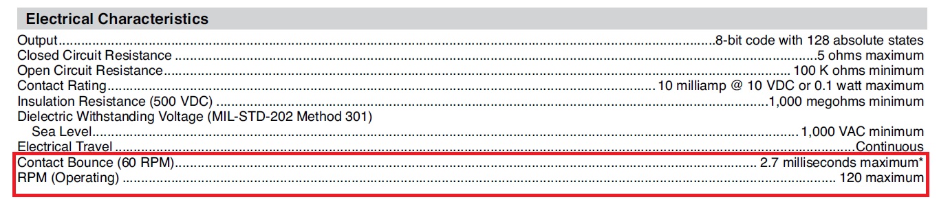
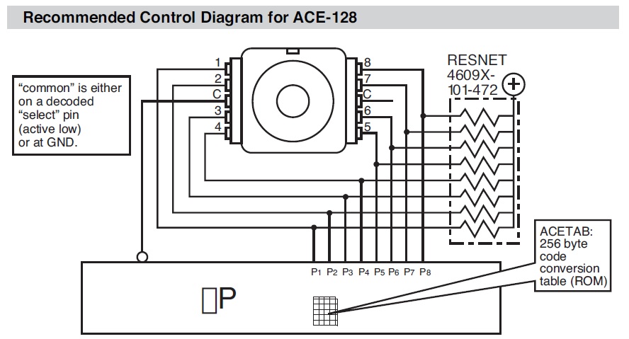
I have EAW - Absolute Contacting Encoder (ACE™) from Bourns and it doesn't return accurate position. There is lot of jumping between values and lot of 255s. That should be problem with wiring but I am pretty sure that wiring is correct, but I might be wrong. Pins 2,3,4,5,6,7,8,9 on Arduino are connected to pins 1,2,3,4,5,6,7,8 on Encoder and C pin on encoder is connected to GND.
Values look like this:

pin 56 raw 4 pos 0 upos 0 mpos 0
pin 184 raw 5 pos 0 upos 0 mpos 0
pin 152 raw 6 pos 0 upos 0 mpos 0
pin 24 raw 7 pos 0 upos 0 mpos 0
pin 72 raw 9 pos 0 upos 0 mpos 0
pin 73 raw 10 pos 0 upos 0 mpos 0
pin 75 raw 255 pos 0 upos 0 mpos 0
pin 43 raw 255 pos 0 upos 0 mpos 0
pin 171 raw 255 pos 0 upos 0 mpos 0
pin 155 raw 255 pos 0 upos 0 mpos 0
pin 25 raw 255 pos 0 upos 0 mpos 0
pin 24 raw 7 pos 0 upos 0 mpos 0
pin 88 raw 255 pos 0 upos 0 mpos 0
pin 8 raw 8 pos 0 upos 0 mpos 0
pin 0 raw 255 pos 0 upos 0 mpos 0
pin 32 raw 104 pos 0 upos 0 mpos 0
pin 162 raw 255 pos 0 upos 0 mpos 0
pin 131 raw 68 pos 0 upos 0 mpos 0
pin 203 raw 46 pos 0 upos 0 mpos 0
pin 138 raw 255 pos 0 upos 0 mpos 0
pin 34 raw 255 pos 0 upos 0 mpos 0
pin 18 raw 41 pos 0 upos 0 mpos 0
pin 83 raw 43 pos 0 upos 0 mpos 0
pin 195 raw 45 pos 0 upos 0 mpos 0
pin 235 raw 47 pos 0 upos 0 mpos 0
pin 227 raw 66 pos 0 upos 0 mpos 0
pin 67 raw 255 pos 0 upos 0 mpos 0
pin 19 raw 54 pos 0 upos 0 mpos 0
pin 3 raw 56 pos 1 upos 1 mpos 1
pin 9 raw 57 pos 0 upos 0 mpos 0
pin 169 raw 59 pos 0 upos 0 mpos 0
pin 225 raw 61 pos 0 upos 0 mpos 0
pin 243 raw 65 pos 0 upos 0 mpos 0
pin 163 raw 67 pos 0 upos 0 mpos 0
pin 129 raw 71 pos 0 upos 0 mpos 0
pin 128 raw 72 pos 0 upos 0 mpos 0
pin 240 raw 77 pos 0 upos 0 mpos 0

Code looks like this:

// Include the encoder library and maps
#include <ACE128.h>  // Absolute Contact Encoder
#include <ACE128map12345678.h> // mapping for pin order 12345678
//#include <ACE128map12348765.h> // mapping for pin order 87654321
//#include <ACE128map18762345.h> // mapping for pin order 87654321
//#include <ACE128map54326781.h> // mapping for pin order 87654321
//#include <ACE128map56784321.h> // mapping for pin order 87654321
//#include <ACE128map87651234.h> // mapping for pin order 87654321
//#include <ACE128map87654321.h> // mapping for pin order 87654321
#include <Wire.h> // I2C bus communication library - required to support ACE128


// Create an ACE128 instance called myACE
ACE128 myACE(2,3,4,5,6,7,8,9, (uint8_t*)encoderMap_12345678);
//ACE128 myACE(38,40,42,44,46,48,50,52, (uint8_t*)encoderMap_12348765);
//ACE128 myACE(38,40,42,44,46,48,50,52, (uint8_t*)encoderMap_18762345);
//ACE128 myACE(38,40,42,44,46,48,50,52, (uint8_t*)encoderMap_54326781);
//ACE128 myACE(38,40,42,44,46,48,50,52, (uint8_t*)encoderMap_56784321);
//ACE128 myACE(38,40,42,44,46,48,50,52, (uint8_t*)encoderMap_87651234);
//ACE128 myACE(38,40,42,44,46,48,50,52, (uint8_t*)encoderMap_87654321);

// set-zero button on pin 13
// - button to ground e.g. MakerShield button
const int ZERO = 13;
uint8_t pinPos = 0; // pin values
uint8_t rawPos = 0;
uint8_t upos = 0;
uint8_t oldPos = 255;
int8_t pos;
int16_t mpos;
uint8_t seen = 0;

void setup() {
  int error = 1;
  myACE.begin();    // this is required for each instance, initializes the pins
  // myACE.reverse(true);  // uncomment this for counter-clockwise operation
  pinMode(ZERO, INPUT_PULLUP);    // configure set-zero button
  pinPos = myACE.acePins();          // get IO expander pins
  oldPos = pinPos;                 // remember where we are
  Serial.begin(9600);
  Serial.println(myACE.acePins());
}


void loop() {
  if (digitalRead(ZERO) == 0) {      // check set-zero button

    // myACE.setMpos(6723);  // set current position to 6723
    myACE.setMpos(0);    // set logical multiturn zero to current position
    // myACE.setZero();     // set logical zero to current position
    // myACE.reverse(true);  // set reverse
    oldPos = 255;                   // force display update
  }
  pinPos = myACE.acePins();          // get IO expander pins
  rawPos = myACE.rawPos();           // get raw mechanical position
  pos = myACE.pos();                 // get logical position - signed
  upos = myACE.upos();               // get logical position - unsigned
  mpos = myACE.mpos();               // get multiturn position - signed

  if (pinPos != oldPos) {            // did we move?
    seen |= pinPos ^ oldPos;         // what changed?
    oldPos = pinPos;                 // remember where we are
    if (seen < 255) {
      Serial.println("looking for pins");
      for (uint8_t i = 0; i <= 7; i++) {
        if (! (seen & 1 << i)) {
          Serial.print(i, DEC);
        }
      }
      Serial.println("");
    } else {
      Serial.print("pin ");
      Serial.print(pinPos);
      Serial.print(" raw ");
      Serial.print(rawPos);
      Serial.print(" pos ");
      Serial.print(pos, DEC);
      Serial.print(" upos ");
      Serial.print(upos, DEC);
      Serial.print(" mpos ");
      Serial.println(mpos, DEC);
    }
  }
}

I tried different maps, different wirings but it is still jumping.
Thanks for advices.

Which Arduino board do you use (it might already use pin 1).
Do you have a ACE-128 ?
Can you give links to the used libraries ?
Do you use a breadboard ? Can you make a photo of it ?

I use this library GitHub - arielnh56/ACE128: Arduino library for Bourns 128 position Absolute Contacting Encoder and Arduino Mega with Ethernet shield.

When there is a problem, fall back to what is the most simple and the most basic.

Please remove the Ethernet shield.
Test every wire with a multimeter, sometimes those wires are broken.
How well do they connect on both sides ?

I read something wrong, sorry. You start with Arduino pin 2, that is okay.

Is that a Arduino Mega 2560 R3 ? If it is not "R3", then you better not use pin 13 as a input.

There is a lot of 0xFF (255) in this table: https://github.com/arielnh56/ACE128/blob/master/src/ACE128map12345678.h. I think that I start to understand the table.

Your output "pin 56" is "Decimal output" 56 in the table in the datasheet. That translates to position 4.
An error occurs when reading "pin 75". In the table in the datasheet is no 75, so you get 255.

The library is too complicated. But so far I can not see any problems.
The library uses separate digitalRead() calls for each input pin, there is a very small chance that something is changing while reading those pins.
There are no external pullup resistors, and the internal pullup resistors are weak. You might get noise.

First of all, you need to be sure that the wires connect. Does something change if you wiggle the wires ? Can you add external pullup resistors of 10k ?
Can you still use the encoder if you simply ignore the 255 ?

Removing Ethernet shield doesn't help.

I tested wires with multimeter and they are good, but i tried multimeter on Encoder pins and there was connectivity between some of them but not all of them, so I tried multimeter on another encoder(bought 2 of them and both jump) and connectivity was between different pins. I don't know if it should be like this but it would be pretty unlucky to buy 2 faulty encoders.

If I wiggle wires nothing happens.

Added 10k resistors and it still jumps.

Ignoring 255 is just one part of a problem because it still jumps between values and it needs to be precise.

The data sheet states there is a high probability of contact bounce. Are you allowing for contact bounce in your program?
Paul

Raw 7 (Pins 24, 0b00011000) is next to Raw 6 (Pins 152, 0b10011000) and Raw 8 (Pins 8, 0b00001000) but in your layout, it is next to invalid Pins 25 (00011001).

Note that Pins 152 (10011000) is the reverse of Pins 25 (00011001). I think you may have the bits numbered backward.

There could be more than one problem.
I would like to do a test without the library.

It this jumpy ? Not tested:

// Combine 8 digital inputs into a byte.
// Arduino pin 2 is bit 0, pin 3 is bit 1, and so on.

int rotPins[8] = { 2, 3, 4, 5, 6, 7, 8, 9};

void setup()
{
  Serial.begin( 9600);
  Serial.println( "The sketch has started");

  for( int i=0; i<8; i++)
    pinMode( rotPins[i], INPUT_PULLUP);
}

void loop()
{
  byte pattern = 0;
  for( int i=0; i<8; i++)
  {
    if( digitalRead( rotPins[i]) == LOW)
      bitSet( pattern, i);
  }
  Serial.print( "0x");
  if( pattern < 0x10)
    Serial.print( "0");
  Serial.println( pattern, HEX);

  delay( 250);
}

It should be. Absolute encoders typically use a Grey Code output where only one bit changes between adjacent positions:

This encoder uses a Grey Code where 50% of the codes are forbidden. That allows for the detection of stuck or misordered bits.

And there are varying unconnected times when moving from switch contact to the next switch contact.
Paul

Debouncing is no implemented, but I don't think that should be the case. In some guides it worked and even in basic library sketch it is not implemented but in my case it's faulty.

This is also jumpy:

0xDE
0xCE
0xC6
0xC7
0x47
0x45
0x85
0x8F
0x8F
0x8F
0x8F
0x8E
0xCE
0xEF
0x6F
0x6D
0x65
0xA4
0xC5
0xC7
0x67
0xF7
0xB6
0xF4
0xD4
0x64
0xE4
0xE6
0xE7
0xB7
0xF7
0xFF

Hi,
Looking at the data in the link;

Page 2, looks like Grey Code to me.
it has a debounce characteristics.

Tom... :smiley: :+1: :coffee: :australia:

Hi, @zokinko
Can you verify with a DMM that the data lines out of the encoder go from 0V to 5V?

I would hope the ACE128 library would turn the internal pullups ON.

Note a reference to a conversion table ROM.

Tom... :smiley: :+1: :coffee: :australia:

1 Like

All pins go from 0V to 4.6V except pin 3. Pin 3 goes only to 0.4V.

That doesn’t really mean a lot without a schematic of how YOUR encoder is wired up.

It's working I changed pin 4 (which was connected to pin 3 on encoder) on Arduino to pin 10 and it works great. I am new to this so I was little confused. I tested wiring before but apparently I did it wrong. Thank you very much guys for help.

I'm glad it is working :smiley:

Was the Ethernet shield attached all the time ?
That uses a number of pins.

I'm sure Bourns makes a good quality rotating encoder, but it uses 9 pins and if one pin fails then it is no longer working. Only a soldered connection or a very good connector should be used.

Even with removed Ethernet shield it was same thing.

But my project is bigger, I use steppers and one of them uses pins 2,3,4 and it works fine, but for some reason encoder doesn't work in that pin.

This topic was automatically closed 120 days after the last reply. New replies are no longer allowed.