AC motor control via VFD

I have a VFD and I am trying to control it with my arduino uno v3

I have connected the VFD with the motor and it works without the arduino.

When I try to connect the arduino with the VFD and run the motor with some code, then nothing happens.

The VFD
https://www.amazon.se/gp/aw/d/B086CWCPPJ?psc=1&ref=ppx_pop_mob_b_asin_title

The AC motor
https://www.amazon.se/gp/aw/d/B096323P1J?ref=ppx_pt2_mob_b_prod_image

I have no experience at all with arduino or VFD. This is my first project. I read some C++ programming in school ~8 years ago. Not much and I was not great. Please keep the level low if you want to help
!

IMG_20250112_142542_HDR|666x500
! :smile:

Are you sure this should be your first project?
It might be dangerous...
High voltage, strong motor...

How did you make the connections?
And what code did you use?

Helpers are not interested in buying the things and wants datasheets, technical manuals etc....
Hopefully You'll get assistance.

Please post a link to the data sheet, instructions and circuit diagram you were following. Post the code, using code tags.

What have you tried and what documentation did you use?

I understand.

Here is the PDF of the manual that I got from the VFD.

The motor i 3-phase and the VFD is powered by 230v.

What I did was:

  1. FWD (VFD) to digital pin 2.
  2. REV (VFD) to digital pin 3.
  3. GND - Arduino GND to VFD GND.

Here is the code i tried:

const int fwdPin = 2; // Forward control
const int revPin = 3; // Reverse control

void setup() {
  pinMode(fwdPin, OUTPUT);
  pinMode(revPin, OUTPUT);
}

void loop() {
  // Start motor forward
  digitalWrite(fwdPin, HIGH);
  digitalWrite(revPin, LOW);
  delay(5000); // 5s forward

  // Reverse motor direction
  digitalWrite(fwdPin, LOW);
  digitalWrite(revPin, HIGH);
  delay(5000); // 5s reverse
}

Maybe something wrong in the settings of the VFD?
The code?
Not strong enough power to the VFD? Do I need a relay or something?

Without a delay between forward and backward, you are actively breaking...
With larger inertia, that could damage your vfd...

Dou you use a 5V arduino?

Hi, @jesperpettersson
Welcome to the forum.

Make a connection from GND to D2, that should ENABLE the drive.
What connections did you make without the Arduino to get it to work?

Connecting Arduino pins may not work.
You need either relay or MOSFET switching between the control pins of the VSD and GND.

It looks like the input is 12V with pull down activation.

Do you have a DMM? (Digital MultiMeter)

Thanks.. Tom.. :smiley: :+1: :coffee: :australia:

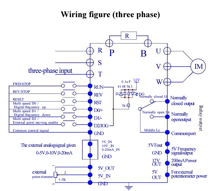
The manual is not super clear, but I think I have it figured it out by now.

The figure suggests GND of the control voltage is connected to the metal parts. These should also be connected to the Protective Earth of the mains. Mains voltage can be harmful. I expect it to be safe, but I hope you'll do some measurements, starting with the connection to the PE before touching the UNO or connecting your PC to the UNO while the drive is powered.

You won't need a separate supply unit for the board if you use the 12V OUT. You can even add some circuitry to the UNO, for instance some buttons and LEDs, up to a 50mA (the board itself needs about 50mA and at 100mA the regulator will start getting warm).

#define pinSpeed 10
#define pinReverse 9
#define pinForward 8

// functions
void setSpeed(int x) analogWrite(pinSpeed, x);
void runForward() digitalWrite(pinForward, HIGH);
void runReverse() digitalWrite(pinReverse, HIGH);
void motorStop() {
  digitalWrite(pinForward, LOW);
  digitalWrite(pinReverse, LOW);
}

void setup() {
  pinMode(pinSpeed, OUTPUT);
  pinMode(pinForward, OUTPUT);
  pinMode(pinReverse, OUTPUT);

  // run a demo
  setSpeed(127);  // half speed
  runForward();   // motor will run one direction...
  delay(10000);   // ...for 10 seconds
  motorStop();    // stop the motor...
  delay(10000);   // ...for 10 seconds
  runReverse();   // motor will run the other direction...
  delay(10000);   // ...for 10 seconds
  motorStop();    // stop the motor
}

void loop() {
  // the demo will run only once
}

Pn 04 - Source of runtime command with range:

This should probably be set to, 2 - External signal control.

For these reasons, I like to use opto-isolators for switching Start/Stop inputs. We'll use relays for industrial applications since PLC outputs are pretty tough, and it's easier to troubleshoot in the field.

May I explain why I suggested the setup I suggested.

  • PE (Protective Earth) was invented to provide — it's in the name — protection. But it needs to be confirmed. Both for personal safety and for compliance with local regulations.

  • OP (Original Poster) did not say it was to be a standalone system, but that's what I'm thinking. Using the inverter for supply of the board negates the need for an supply unit. Already having a connection for supply negates the need for optical isolation.

  • Using an optical isolator for the analog signal will be not very linear, or not simple. Using industrial grade units for isolation might make the connections more expensive than the items to be connected.

  • OP got it working using the panel so he might be familiar with parameter settings.

More info from OP will allow us to hone in on what he exactly needs.

That could damage the Arduino, given that the FWD and REV pins are internally connected to 12V via a 5K resistor and an LED.

It is much safer to use an NPN transistor as a switch:

Or even better, an optocoupler. Then there is no need to connect the Arduino and VFD grounds.

2 Likes

Thank you! I'll get the equipment and give this a try :slight_smile:

This topic was automatically closed 180 days after the last reply. New replies are no longer allowed.