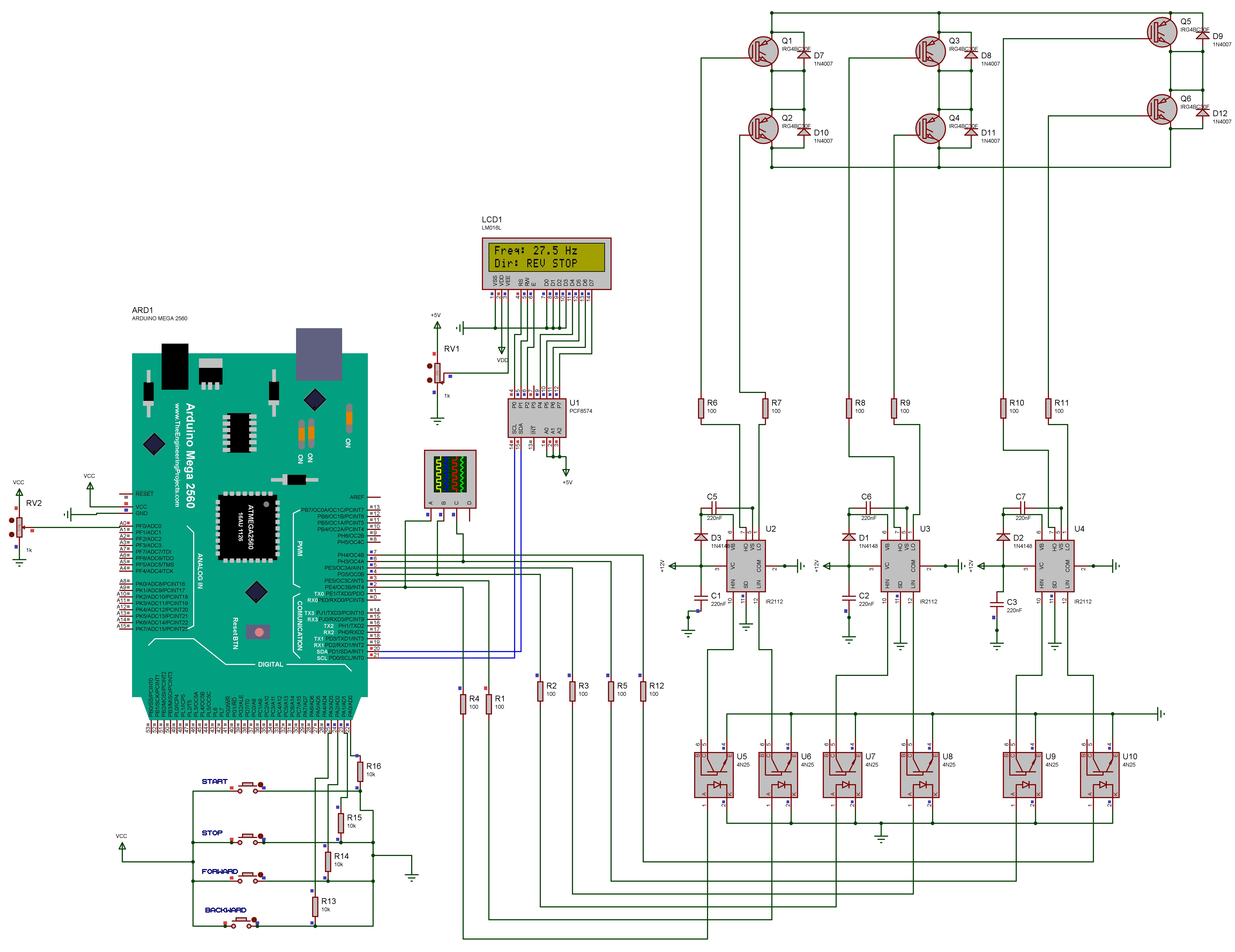
Hello , so i design this circuit about vfd , ![]() wrote the code and the buttons are not working (only the potontionmeter) so i used a line in the code "running=true;" so the signs works ,
wrote the code and the buttons are not working (only the potontionmeter) so i used a line in the code "running=true;" so the signs works ,
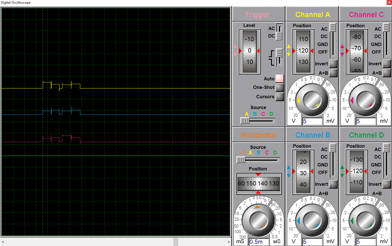
now there is the oscilloscope linked to the inverter and that's the sign i'm not sure its the right sign because i added a leds to make sure it works and to make it clear to you the pwm sign are work
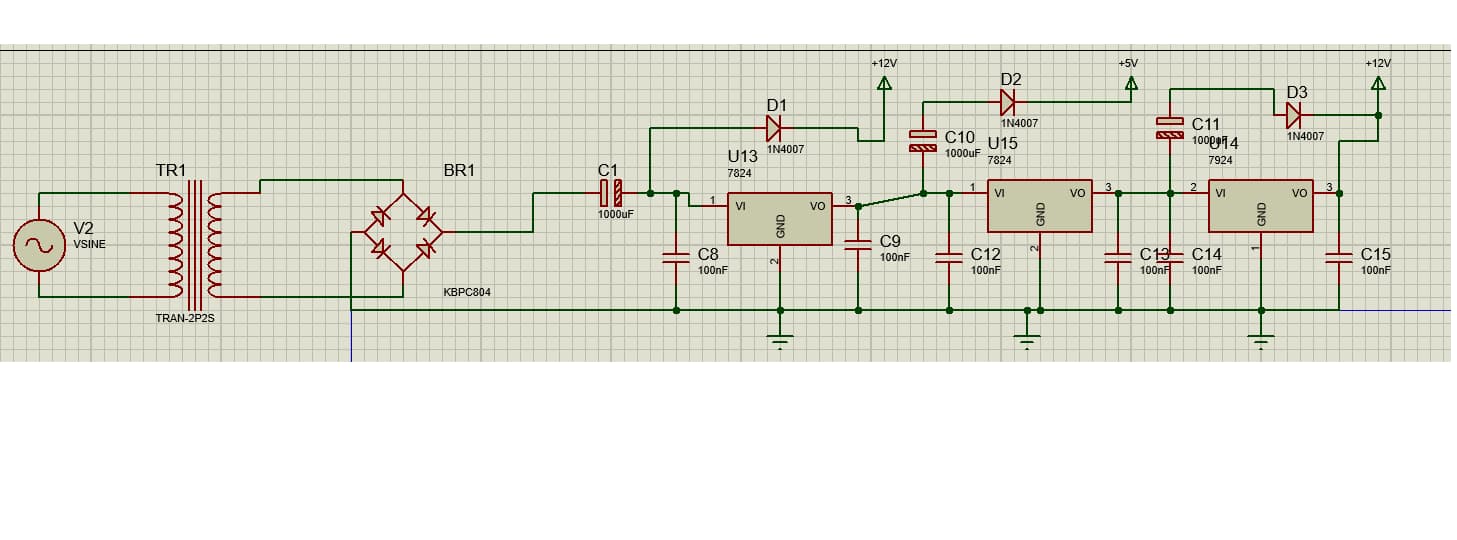
![]() and my final question is i know i must add the ac source and voltage regulator ... etc , is it right and if it is how i will link it to the circuit
and my final question is i know i must add the ac source and voltage regulator ... etc , is it right and if it is how i will link it to the circuit
and this is the code because i cant share the ide file here
#include <Wire.h>
#include <LiquidCrystal_I2C.h>
#include <math.h>

// LCD at I2C address 0x27, 16 columns, 2 rows
LiquidCrystal_I2C lcd(0x27, 16, 2);

// --------- Pin Definitions ----------
#define A_H 2
#define A_L 3
#define B_H 4
#define B_L 5
#define C_H 6
#define C_L 7

#define START_BTN    22
#define STOP_BTN     23
#define FORWARD_BTN  24
#define BACKWARD_BTN 25

#define POT_PIN A0

// --------- Constants ----------
const int TABLE_SIZE = 100;
float sineTable[TABLE_SIZE];

const float BASE_FREQ = 50.0;  // 50 Hz base
const int DEAD_TIME_US = 3;
const unsigned long DEBOUNCE_DELAY = 50;
const unsigned long LCD_UPDATE_INTERVAL = 200;

// --------- State Variables ----------
bool running = false;
bool directionForward = true;
unsigned long lastMicros = 0;
int stepIndex = 0;
float currentFreq = BASE_FREQ;
unsigned long stepTime = 0;
unsigned long lastDebounceTime = 0;
unsigned long lastLcdUpdate = 0;

// --------- Setup ---------
void setup() {
  // Setup PWM output pins
  pinMode(A_H, OUTPUT);
  pinMode(A_L, OUTPUT);
  pinMode(B_H, OUTPUT);
  pinMode(B_L, OUTPUT);
  pinMode(C_H, OUTPUT);
  pinMode(C_L, OUTPUT);

  // Setup input buttons
  pinMode(START_BTN, INPUT_PULLUP);
  pinMode(STOP_BTN, INPUT_PULLUP);
  pinMode(FORWARD_BTN, INPUT_PULLUP);
  pinMode(BACKWARD_BTN, INPUT_PULLUP);

  // Generate sine table
  for (int i = 0; i < TABLE_SIZE; i++) {
    sineTable[i] = (sin(2 * PI * i / TABLE_SIZE) + 1.0) / 2.0;
  }

  // Setup LCD
  lcd.init();
  lcd.backlight();
  lcd.setCursor(0, 0);
  lcd.print("3-Phase SPWM VFD");
  delay(1000);
  lcd.clear();
}

// --------- Button Debouncing Function ---------
void readButtons() {
  if ((millis() - lastDebounceTime) > DEBOUNCE_DELAY) {
    if (digitalRead(START_BTN) == LOW) {
      running = true;
      lastDebounceTime = millis();
    }
    if (digitalRead(STOP_BTN) == LOW) {
      running = false;
      lastDebounceTime = millis();
    }
    if (digitalRead(FORWARD_BTN) == LOW) {
      directionForward = true;
      lastDebounceTime = millis();
    }
    if (digitalRead(BACKWARD_BTN) == LOW) {
      directionForward = false;
      lastDebounceTime = millis();
    }
  }
}

// --------- Display Update ---------
void updateDisplay() {
  if (millis() - lastLcdUpdate > LCD_UPDATE_INTERVAL) {
    lastLcdUpdate = millis();

    lcd.setCursor(0, 0);
    lcd.print("Freq: ");
    lcd.print(currentFreq, 1);
    lcd.print(" Hz    ");

    lcd.setCursor(0, 1);
    lcd.print("Dir: ");
    lcd.print(directionForward ? "FWD " : "REV ");
    lcd.print(running ? "RUN " : "STOP");
    lcd.print("    ");
  }
}

// --------- Speed Control ---------
void updateSpeed() {
  int potValue = analogRead(POT_PIN);
  float speedScale = map(potValue, 0, 1023, 10, TABLE_SIZE) / float(TABLE_SIZE);
  currentFreq = BASE_FREQ * speedScale;
  stepTime = 1000000.0 / (currentFreq * TABLE_SIZE);
}

// --------- Dead-Time PWM Output ---------
void writeSPWM(float duty, int pinHigh, int pinLow) {
  int onTime = duty * stepTime;
  int offTime = stepTime - onTime;

  if (onTime > DEAD_TIME_US) {
    digitalWrite(pinHigh, HIGH);
    delayMicroseconds(onTime - DEAD_TIME_US);
    digitalWrite(pinHigh, LOW);
  } else {
    delayMicroseconds(onTime);
  }

  delayMicroseconds(DEAD_TIME_US);

  if (offTime > DEAD_TIME_US) {
    digitalWrite(pinLow, HIGH);
    delayMicroseconds(offTime - DEAD_TIME_US);
    digitalWrite(pinLow, LOW);
  } else {
    delayMicroseconds(offTime);
  }
}

// --------- SPWM Generation ---------
void generateSPWM() {
  unsigned long now = micros();
  if (now - lastMicros >= stepTime) {
    lastMicros = now;

    int indexA = stepIndex;
    int indexB = (stepIndex + TABLE_SIZE / 3) % TABLE_SIZE;
    int indexC = (stepIndex + 2 * TABLE_SIZE / 3) % TABLE_SIZE;

    float dutyA = sineTable[indexA];
    float dutyB = sineTable[indexB];
    float dutyC = sineTable[indexC];

    if (running) {
      writeSPWM(dutyA, A_H, A_L);

      if (directionForward) {
        writeSPWM(dutyB, B_H, B_L);
        writeSPWM(dutyC, C_H, C_L);
      } else {
        writeSPWM(dutyC, B_H, B_L);
        writeSPWM(dutyB, C_H, C_L);
      }

      stepIndex = (stepIndex + 1) % TABLE_SIZE;
    } else {
      digitalWrite(A_H, LOW); digitalWrite(A_L, LOW);
      digitalWrite(B_H, LOW); digitalWrite(B_L, LOW);
      digitalWrite(C_H, LOW); digitalWrite(C_L, LOW);
    }
  }
}

// --------- Main Loop ---------
void loop() {
running=true;
  readButtons();
  updateSpeed();
  updateDisplay();
  generateSPWM();
}