AC Voltage Measurement - I'm trying to keep it simple

AC Voltage Measurement - I'm trying to keep it simple.


Reference URL

  1. ZMPT101B schematic review
  2. https://diyprojectslab.com/zmpt101b-voltage-sensor-module-with-arduino/
  3. AC Line voltage measurement circuit

@jim-p
hello.
I'm trying to make 'AC voltage measurement' simple.

  1. I would like to configure the circuit without ‘OP AMP’.
  2. Voltage measurement range: 50~400VAC
  3. Accuracy: Is it possible to achieve 1%?

[circuit]
R1: 400k
R2: 2k
Vout: about 2V(peak?)
C1: 22pF

[board]
STM32Duino
12bit ADC
Operate voltage : 3.3VDC

Please advise.

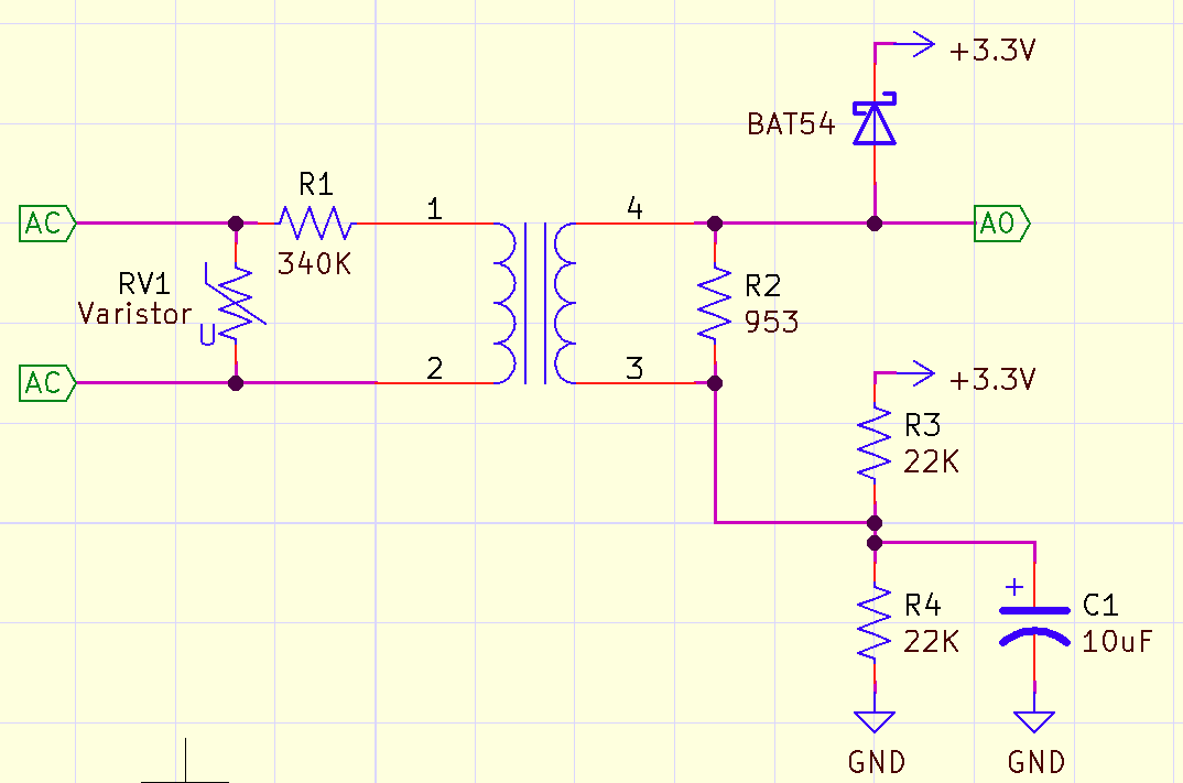
The ADC input will swing negative half of the time. It'll probably work OK if you out a series resistor on it. I'd personally also add a Schottky diode on the ADC input to prevent it from swinging lower than -300mV. Note that you need the additional resistor along with this.

What's the AC frequency?

1 Like

This is the best you will get without an op-amp

1 Like

@rsmls
I am truly grateful every time.
The reason is that they are interested in my writing.
Thank you.

  • INFO: 380VAC, 60Hz.

'swing negative half of the time'
Thank you.

@jim-p

  • I understand your schematic. Thank you.
  • You seem to be good at giving the other person the answer they want.
    Has a high level of feeling or insight. (It seems like he has a lot of skill or has dealt with a lot of people.)

@jim-p

hello. In order to minimize the circuit, I would like to configure it as shown in the picture.
Q1) Can 1.65V be used in common?

I would add another BAT54 between A0 and ground (anode to ground). With one diode you only clip the positive part of the wave, not the negative part, which is equally destructive.
Leo..

1 Like

@Wawa, @jim-p

Does this mean that 1.65V be used in common should not be used in common?

Isn’t it okay to not have the ‘BAT54’ element?
I think it was put in for safety reasons.
Am I wrong?

Yes.

1 Like

This is what @Wawa meant.
Add another BAT54

1 Like

Hi @myksj

380Vac is that RMS or peak.

ZMPT101B is rated for;

Tom.. :smiley: :+1: :coffee: :australia:

1 Like

Tom,
That rating of "up to 250V" is for the module.

I believe that myksj is using the bare transformer alone, (maybe he'll correct me if I'm wrong), so that limit does not apply.


The transformer itself operates at a low voltage, and current up to 2mA.
The majority of the voltage is dropped across the series resistor on the input.

High voltage techniques should be used when building the circuits suggested.
Use several resistors in series to make up the 340kΩ, as standard resistors are generally rated at 200V or less.

1 Like

@jim-p
Thank you for answer.

  1. ‘bat54’ is known as a safety circuit.
  2. Isn’t it functionally unnecessary?

@TomGeorge, @JohnLincoln
Thank you for answer.

  1. I'm going to proceed like '@JohnLincoln' said.
  2. Resistance value : 380K(value) =~ 200k(1W) + 200k(1W)
  3. 380V applied voltage = V1(R1) + V2(R2) + V3(ZMPT)

I'm trying to configure it as above. I don't think there will be any problem in terms of internal pressure.

@jim-p, @Wawa, @TomGeorge, @JohnLincoln

Sorry for mentioning it again and again. I don't know much, so please forgive me.

I have a question.

  1. '@jim-p''s circuit is similar to a current measurement circuit.
  • Current CT circuit
    figsss

  • The current value can be measured with 1% accuracy through the corresponding current measurement circuit and coding.

  • This is possible through a passive circuit without an 'OP Amp'.

  1. It doesn't matter when measuring current, but it becomes a problem when measuring 'leakage current'.
    https://www.alibaba.com/product-detail/Acrel-AKH-0-66-Leakage-Current_1600850805978.html?spm=a2700.galleryofferlist.normal_offer.d_title.577d1d18Vbm0CG
    (1) I understand that ‘Leakage Current’ must be measured in uA units.
    (2) Looking at the product specifications,
  • Reference current: 1~5000A.etc
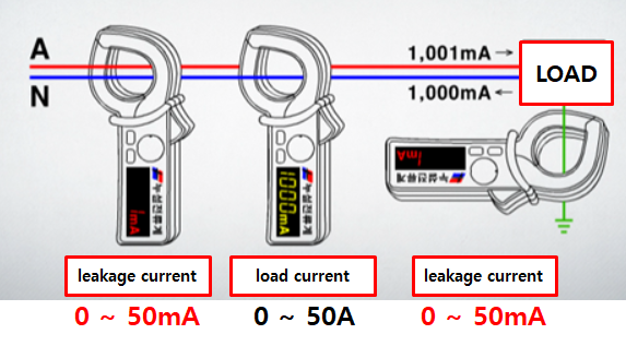
  • Current ratio: 1A/1mA
    Q1) In my opinion, the smaller the measurement range, the higher the accuracy, right?
    Q2) Also, doesn't the accuracy increase as the 'Current ratio' is 1A/1uA?
    Q3) In conclusion, I think what I'm curious about is that the range of 'Leakage Current' is to measure 0 to 50mA.
    However, when I look for products, I don't understand why the current measurement range is high. Am I thinking wrong? Or maybe I couldn't find the 'CT' or 'ZCT' I wanted.

Q4) Also, I would like to implement the first stage amplifier circuit with ‘LM358’.

All your questions have to do with measuring small currents. CTs are not the only current measuring sensor. Where is this small current you want to measure?

1 Like

@jim-p

figs
Thank you for answer.

This is to measure leakage current.
Please check the image.

There are CTs designed for use in GFCIs (Ground-Fault Circuit Interrupter) that can measure those small leakage currents. You may want to google "GFCI current transformer" and "GFCI circuits"

1 Like

@jim-p
Let's take a look. thank you

This topic was automatically closed 180 days after the last reply. New replies are no longer allowed.