hey everybody!
i searched the forum and online but havent been able to figure out a problem i am having.
i have an adxl345 accelerometer connected to a teensy 3.1 and i want to use the accelerometer as a midi controller
in combination with other sensors, in this case 8 bend sensors as we as an accelerometer.
i connected the adxl345 to the teensy before hand, and the sensor output was amazing, very stable plus 1,0,-1 at rest (about, etc.
however, i breadboarded the whole project now (plus the 8 bend sensors on 12k resistors as well as the infrared sensor and a vibration motor on a diode)
and suddenly the output of the accelerometer becomes very jittery (+20,0,-20 and more at rest), i tried out another teensy
plus accel in the same setup -> same problem, and both teensy and accel seperately on a dfferent breadboard, same code
but without the other sensors plugged in. the voltage going into is very stable on bothe breadboards.
now, it seems clear to me that the chips are not the reason for the problem, the code neither.
could the sensors be responsible for the jittery values? maybe the vibration motor, even though the diode should prevent any current problems..?
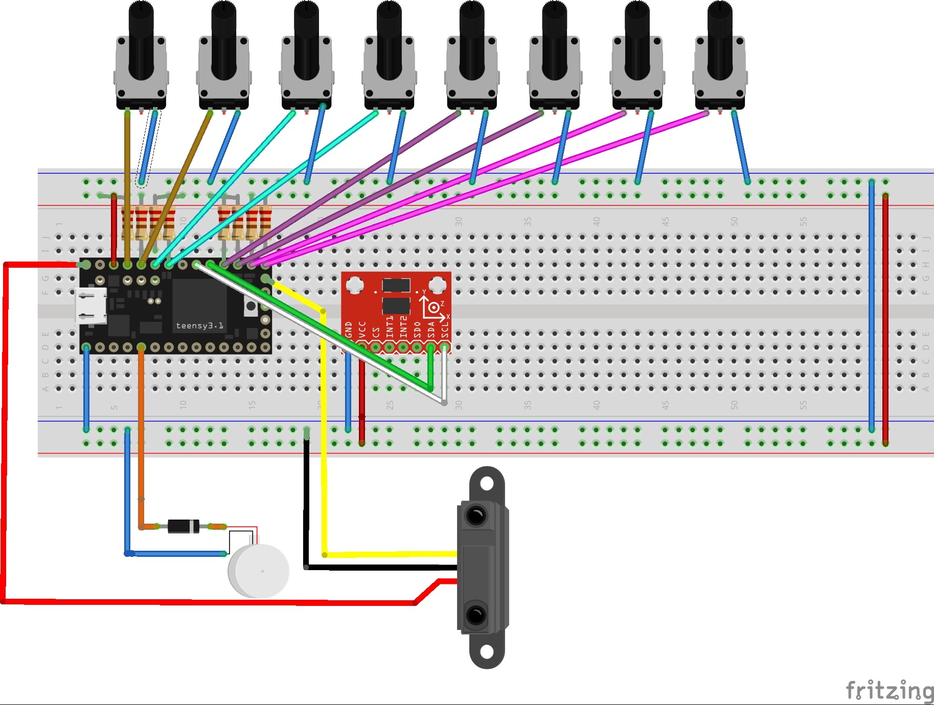
the bend sensors are on A9-A6, and A3-A0, the infrared sensor on A14, vibration motor on Pin3,
the accel on SCL0 and SDA0.
i am new to programming as well as electronics and i would appreciate any help or advice on how to find the problem!
if you think a photo is useful, ill be happy to post one
Hey! First of all, thank you for your answers! @awol
Yeah, the sensors where identical, the code and the chips too, I didnt not change the range.
(I wouldnt know how to do that anyways... )
in both cases the accelerometer remains at rest, with the other sensors not connected it has a very stable output, with bend sensors, motor and infrared sensor connected the output becomes very jittery.
@tom
“If you run the same sketch without all the sensors but for the adxl345 , the readings are stable, am I right? “
yes, exactly!
“Can you please post a copy of your circuit, in CAD or a picture of a hand drawn circuit in jpg, png?“
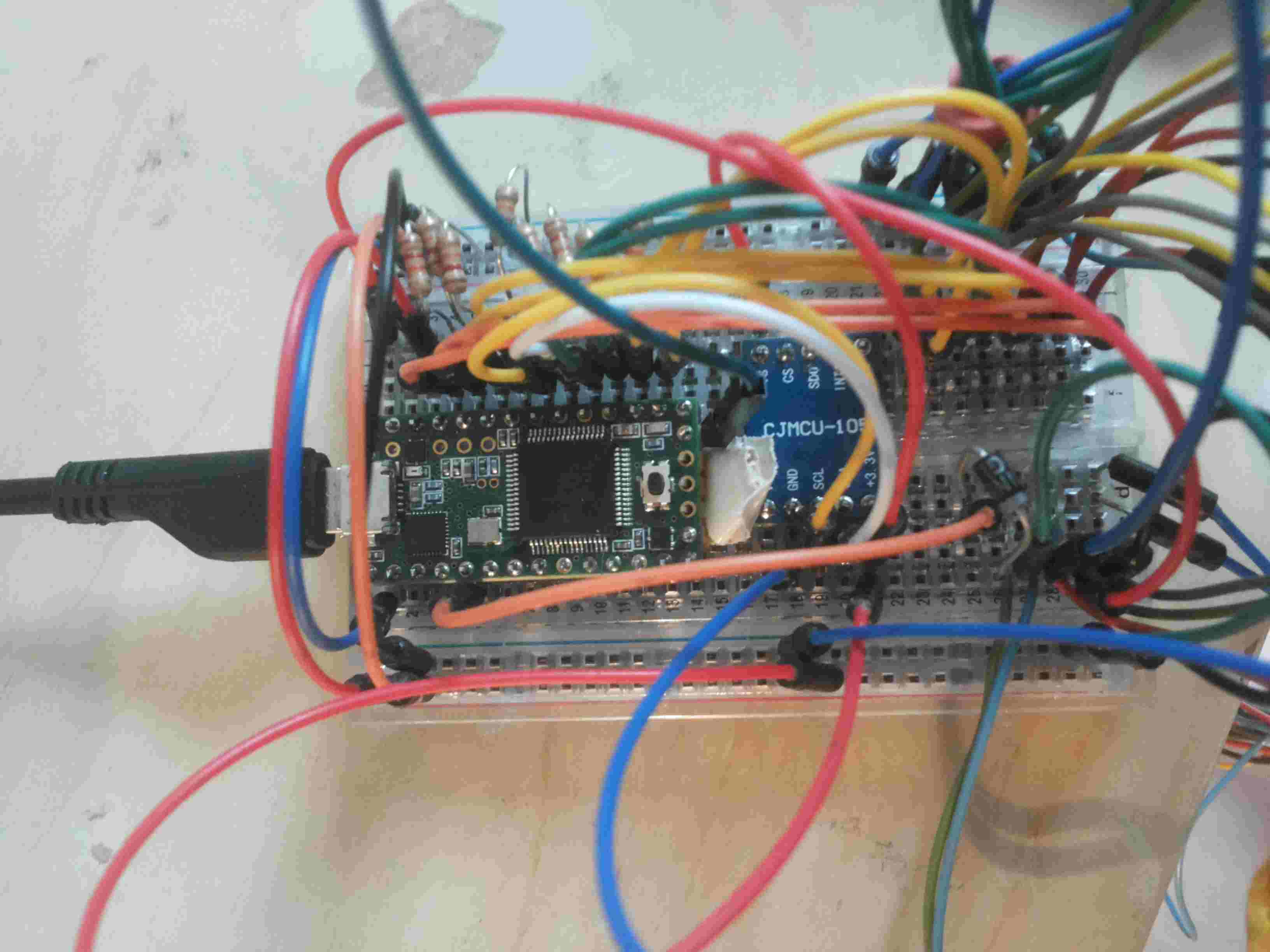
Yes, photos and fritz below (im new to electronics, so I apologize for any mistakes in the fritzing..)
no, im not using a capacitator, I might later on even though I would rather keep smoothing digital since the chips will be part of the glove, so any additional hardware will just make it bulkier. In any case, since I do get a very stable output from the accelerometer by itself, I first want to try fixing the problem as it is.
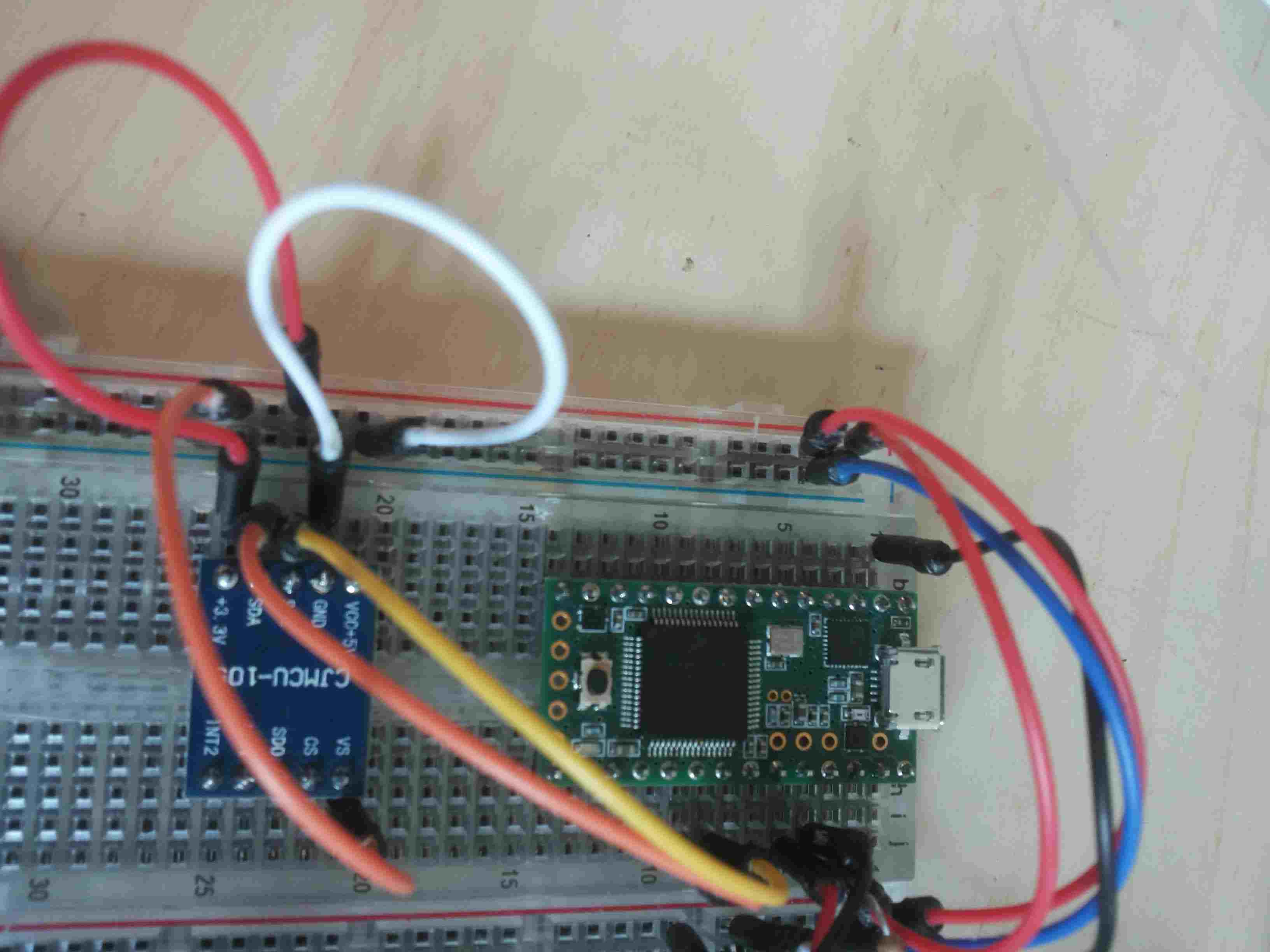
The resistors are 12.6k, and as you can see from the photo the accelerometer is a different one, but I can assure you it is connected correctly. The infrared sensor is connected to the 5v channel, but that hasnt been a problem before either. The last photo shows the setup on a different board with the same chips. the bend sensors in the fritzing are represented as pots.
@jremington
really? Ok, I didnt know that... I did get the code from the arduino home page:
its just a tiny 3/5 volt motor... (How to Build a Vibration Motor Circuit)
I dont think it should be a problem. Plus I secured it with a diode so the pin is protected:
Hi,
This will be because the ADXL354 will have some bypassing and DC filtering capacitors on it.
By fitting the diode you isolate to some extent the variations or noise the the other loads are putting on the 5V supply.
As I suggested on post #2 for you to add bypassing to the power input of the ADXL354.
The diode on the motor is also wrong, It should be in parallel with the motor, cathode to the positive end of the motor, anode to the negative end of the motor.
Uh, ya, putting the diode on the motor like that probably makes things worse, not better. And you shouldn't switch a motor directly with an IO pin, use a transistor or fet to switch it.
Also - put some caps on for power supply filtering and bypassing - some small ceramic ones right near the accelerometer, and maybe a larger electrolytic (couple hundred uf?) on the supply for filtering.
hey! thanks for your replies! sorry if i made stupid mistakes, but again, i just started working on electronics so i have little knowledge concering volts, capacitators, etc. your help is much appreciated though!
Did you read and look at it?
uhm, to my shame, i actually did... but then i looked at another sketch where the motor was connected the same way that i connected it (wrongly it turns out) and i liked that second sketch better.. heh hoped i would get away with that( and until it worked without breaking anything), but now i will of course copy the correct setup!
thx again! just one last question, do you always use diodes in parallel or is the way i connected it to the adxl345 correct?