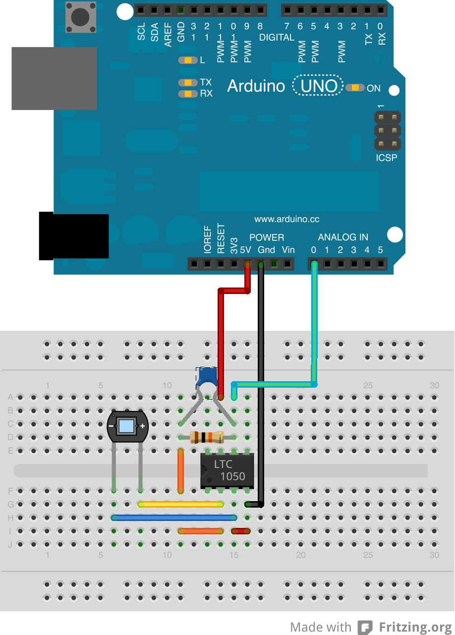
and did some adjustments by putting 1M ohm resistor from pin3 to GND:
I just once somehow managed to get almost same readings where values changed +-2 or so. But now its really inaccurate
I changed capacitors, resistors, almost anything but nothing helped. So please if you have any suggestions.. I really appreciate if you can help me to find a solution for this problem.
That Fritzing diagram is not a "schematic." These are schematics:
You might get better help if you post a "real" schematic with the values of your components, and your code.
Also, have you tried plotting your values vs time? Are they periodic? If so, what is the frequency? What is your light source? Could it have a flicker that is periodic?
What's your light source? - if mains powered you could easily have variations. try increasiing the capacitor value. Or testing with a dc powered or natural light source
Ambient light problems?
Take two readings throw away the first.
Add a 10K from the Arduino input to ground.
Us a running average.
Remove the diode add an appropriate resistor in its place to see if there is cct. noise.
jremington: I answered them already but:
Here is graph I took from reading. They are not periodic, and I'm using DC powered high power LED. Y-axis is just reading from analog, X-axis is each readings after 300 milliseconds.
allanhurst: Light source is DC high power LED. I also used flashlight powered by batteries and same results. And natural light source... I tried to go outside and same results again.
LarryD: Ambient light is almost zero, I'm working in dark room with lights on just when I'm doing something with board. When I'm taking measurements I switch off all lights except the LED one.
I added 10k from arduino input to GND and just slight improve.
I removed diode but I couldn't find appropriate resistor I always get 0.
jremington: Yes I do, otherwise I would get just zeros
Although I don't have experience with phototiodes, noise is a normal part of the "analog world" and your readings don't look too bad to me. For example, if the light level increases by 20%, I think you can detect that and measure the difference. I assume you get different readings with zero light?
With a photodiode you've got a tiny signal you tend to get a poor signal-to-noise ratio. The amplifier will add some noise and it amplifies the noise along with the signal.
Some low-pass filtering will help. The [u]Smoothing Example[/u] shows you how to do moving-average filtering which is a kind of low-pass filtering. You could also add an analog filter, but software filtering is probably easier.
DVDdoug: You're absolutely right. BUT. Once I've assembled it IT WORKED. It was maybe some kind of magic but when I read I've got like 500 and +-1, seriously. But when I wanted to do my own pcb and screwed it, I bought just another type capacitor but with same capacitance and now there's that problem.
And yes... problem is, even with no light I still ?something? measure. And yes it's not that too terrible, but when I'll calculate absorbance it really depend. If arduino show me some number with -5% tolerance and then take another measurement with +5% tolerance, it can lead to serious miscalculations.
jremington: Well I need to be sure, that I will read always more/less same number to see if it respond well.
Here you can see my setup. Problem is, I can't increase light level because, light must be diffracted in proper way. And what's even worse, LED has very variable wavelength intensity but I know that and that's not big deal.
jremington:
The angle of diffraction depends on light wavelength, not light intensity.
Yes, I said it wrong... The point is that even in commercial spectrometers, they are using incandescent bulb. I'M using high power 10W LED so I think I can't get even higher because I would have to deal with lots of heat. Anyway I don't know where's problem. In amplifier probably not, in resistors definitely not... wiring also not I checked everything. I even used different cables to connect my arduino, no .. it didn't changed anything
What are you actually trying to do, and what does a 10 watt LED have to do with it?
Commercial spectrophotometers analyze light in terms of intensity versus wavelength. The light could come from a distant star, or any light source nearby.
jremington:
What are you actually trying to do, and what does a 10 watt LED have to do with it?
10W LED is my light source, that's just it, and I think it's powerful enough. I bought quiet sensitive diode and amplifier with low input noise. Maybe I didn't explained what's my goal. I really need to relay on precise measuring of my not yet build spectrometer. The point is to get "almost" same results even if I'll measure one sample five-times, ten-times. So if I have same sample and measure it firstly to get 200, second 201, third 202, forth 200 again, etc...
(precision measuring) <> (Arduino 10-bit ADC + breadboard + long wires + non-ratiometric sensor + wall wart power supply(?))
PS: judging from responses, the problem probably is "noise" and not periodicity of the light source or ambient, but in the future if you are interested in determining whether there is, for example, "mains" interference at 50 Hz or 60 Hz, delete the 300 ms delay.
DaveEvans:
(precision measuring) <> (Arduino 10-bit ADC + breadboard + long wires + non-ratiometric sensor + wall wart power supply(?))
PS: judging from responses, the problem probably is "noise" and not periodicity of the light source or ambient, but in the future if you are interested in determining whether there is, for example, "mains" interference at 50 Hz or 60 Hz, delete the 300 ms delay.
And is there any way how to reduce that noise or smooth it? I know I can't expect miracles with (Arduino 10-bit ADC + breadboard + long wires + non-ratiometric sensor + wall wart power supply(?)) but at least some accuracy.
Thank you for that determining interference.