Currently I'm making a dyno for RC-cars. With this dyno I want to measure the current that the battery deliveres to the motor so I can calculate the engine power and torque.
I'm using the ACS 712 sensor and the sensor doesn't give a clear value. A current clamp says that the battery deliveres around 18 Amps when the motor is running but the arduino says it only delivers around 0.9 Amps.
Has this to do with my code, with the sensor or can't te ACS 712 measure from a brushed DC motor?
This is my code:
int mVperAmp = 185;

const int sensorIn1 = A8;

double Voltage1 = 0;
double VRMS1 = 0;
double AmpsRMS1 = 0;

void setup() {
  Serial.begin(9600); //Start Serial Monitor to display current read value on Serial monitor
}

void loop() {
 Voltage1 = getVPP1();
 VRMS1 = (Voltage1/2.0) *0.707;
 AmpsRMS1 = (VRMS1 * 1000)/mVperAmp;

Serial.print(AmpsRMS1);
}

float getVPP1()
{
  float result1;

  int readValue1;             //value read from the sensor
  int maxValue1 = 0;          // store max value here
  int minValue1 = 1024;          // store min value here

   uint32_t start_time1 = millis();
   while((millis()-start_time1) < 250) //sample for 0.250 Sec
   {
       readValue1 = analogRead(sensorIn1);
       // see if you have a new maxValue
       if (readValue1 > maxValue1)
       {
           /*record the maximum sensor value*/
           maxValue1 = readValue1;
       }
       if (readValue1 < minValue1)
       {
           /*record the maximum sensor value*/
           minValue1 = readValue1;
       }
   }

   // Subtract min from max
   result1 = ((maxValue1 - minValue1) * 5.0)/1024.0;

   return result1;
 }
Your topic has been moved to a more suitable location on the forum. Installation and Troubleshooting is not for problems with (nor for advice on) your project See About the Installation & Troubleshooting category.
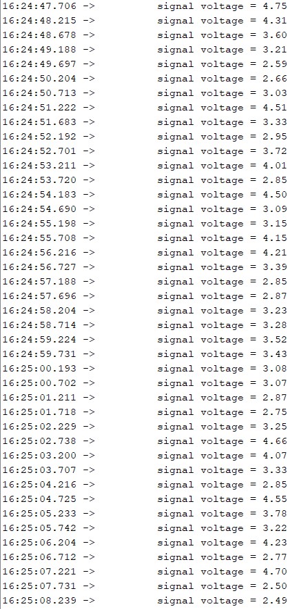
To check the signal i did some tests with the following code:
void setup() {
  Serial.begin(9600);
}

void loop() {
Serial.print("\t signal voltage = ");
Serial.println(5/1024.0*analogRead(A8),2);
delay(500);
}
During this test the current clamp measured between the 10 and 12 Amps. the results from the arduino are below, the ACS 712 has a max Amp rate of 20 Amps
how do the Arduino readings compare with the current clamp?
The current clamps I have only measure AC - what is your clamp to measure DC?
do you have a standard ammeter which can fit in the supply cable?
Your code in post#1 is for AC, and won't work for DC.
This test sketch should work with a 5volt-logic Arduino and a 20Amp ACS712.
If the readout from this sketch is not correct, then it could be PWM of the motor/driver.
That can be fixed with smoothing code (multiple samples).
Leo..