I'm looking to make a simple, low-cost water sensor, that can sense whether a container has water in it, or not. This is to be attached to the outside of the container (a 2-3 mm plastic wall, no metal, water with ionic nutrient solution) and all I want it to do is sense whether there's water on the other side or not. By placing this sensor some 5 cm above the bottom it can act as "I'm almost empty, please fill me up" alarm.
It's supposed to be contactless and out of the water, which is why I'm looking at capacitive sensors. The best bet seems to be an active shield type of sensor, as described in this document. I'm mostly looking at topology b), where ground and sensor traces are placed next to one another (possibly multiple as interlocking fingers, to increase overall capacity and sensitivity), and a shield on the other side.
The description is promising: sensitivity is highly directed to one side (the container), no sensitivity on the outside (so no issues with approaching hands or so).
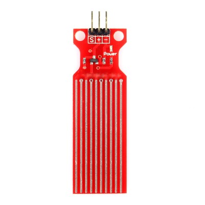
I've been searching for schematics on how to make this work, and seemingly the simplest solution is a combo of a 555 and an opamp (see link above), where the 555 produces the signal and the opamp copies this to drive the shield. A microprocessor can then be used to count the frequency, and do something with it. Looks easy enough to build this circuit; I have some LM538M opamps and TSL555CN timers. For sensor I was thinking of cutting the head off of a a cheap water sensor, adding a piece of aluminium foil to the back of that PCB as shield.
Now I'd love to remove this OpAmp/555 combo and let an ESP8266 control the sensor: producing the signal for both the shield and the sensor, and then sensing the result. If it works, I'm hoping to use an ATtiny or similar microcontroller for this, as all it has to do is operate the sensor and switch (blink?) an LED. Power is not an issue as it's to be powered off a 12V adapter, of course with appropriate regulator and so.
The big problem I have is how to synchronise the signals to the shield and the sensor plate, and at the same time measure the capacitance of the sensor plate.
Can this be done? If so, how?
Any references to someone that did this already? My Google searches came up shockingly empty. It's hard to imagine I'm the first to try this, as low-cost sensors that appear to be using this principle are available.


