Hello,
I've building a AD2S1210 module.
I would like to read resolver position and velocity using serial SPI.
Because I'm building the module, I would like not to make errors on hardware. For this reason I ask you if what I have to expose to the MCU are the following pins:
SCLK, SDI, SDO, CS for the SPI data transfer
SAMPLE to request a sample data while not reading from SPI
WR to start reading from SPI
SOE will by tied down to GND cause I only need the SPI serial output.
RES0 and RES1 always to VCC, cause I plan to set excitation frequency by SPI.
RD is always to VCC cause by datasheet when SOE is low RD can stay high.
A0 and A1 always to VCC, cause my plan is to make the device work always in configuration mode.
Do you think there's will be some problem running the device always in configuration mode? By datasheet seems acceptable.
I've read this post here, but I don't find there all the information i need.
You don't need the level converter for the UNO. If you're using another Arduino board you forget to mention that.
If you use the level converter you should connect the enable pin to the CS line to bring the MISO line tri-state if the device is diabled.
I don't see the reason for the opto-couplers. Are they an expensive variant of the level converter?
Hello.
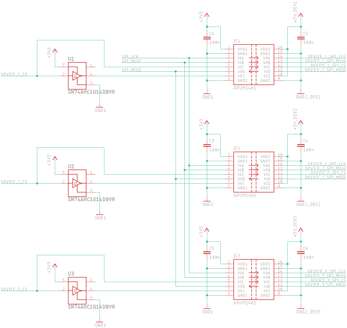
To decouple grounds, isolators are used (here TPL2662 which is a fast optocoupler, and the ADUM1401 which is specifically for SPI). In this way the GND and signales from the board, the following
AD2S1210_SAMPLE, AD2S1210_WR, SPI1_SCK, SPI1_MOSI, AD2S1210_CS, SPI1_MISO have GND1 (the one of the microcontroller), meanwhile all the other wires have the ground of the resolver. It means that the microcontroller unit is fully protected from any voltage problem on the resolver.
You can also forget about those isolator and connect directly to the board the signals from the AD2S1210 named: SAMPLEN, WRN/FSYNCN, CS, SCLK, SDI, SDO.
I haven't searched for the datasheet of the ADUM1401 so I didn't realize that it's an isolating level converter.
But it's still wired wrongly. It will work this way if that's the only device on the SPI bus and this will stay so but even in that case I would wire it correctly and tri-state the ADUM1401 if CS is pulled high.
I again insist on the Arduino. The voltages are wrong for the UNO so I assume you're using another board but you repeatedly failed to tell us what board that is.
Thank you.
I'm sorry but It does not get in my mind that the MCU board is so important, cause due to the isolators I can simply connecting the ADUM1401 and the two optocoupler to +5V on the microcontroller side, or use a shifter if needed. By the way the plan is to use this board with an Arduino GIGA, which I think has 3.3V I/O support.
I've used the ADUM1401 in a previos configuration in the way you see wired here, but it was one device only. I've to investigate further in case multiple device are used.
What about the AD2S1210? Do any have any suggestion on that?
No, I guess it should work that way what you want to use it for.
Theoretically you can eliminate the second opto-coupler as the FSYNC signal is used as the standard CS signal, for this chip CS can be constantly low (although that's quite strange for an SPI device).
Thank you!
I'll build the test board with WR connected, then I'll check if I need or not to use that.
Also thanks for pointing me out the SPI bus problem. I've ended up using the bus attached (this will be a generic one for 3 devices).