Adafruit 1141 (Datalogger+RTC, new version) with Dué ⸺ "Couldn't Find RTC"

Hardware:
Adafruit 1141 (genuine; RevB).
Arduino Dué (genuine)


This is an outgrowth from my prior post (see using XD-204 "old version" datalogger).

I had challenges getting the generic XD-204 datalogger (it's a clone of the old version of the Adafruit datalogger + RTC shield) . In short, I got the clone to work but it does not have on-board traces for the SPI port of the Arduino Dué. The Rev B (part 1141) from Adafruit has the SPI port connected by on-PCB traces.

From what I understand, the SD datalogger connection is making use of the 6-pin SPI connector. The SD card Examples supplied by the SD Card Library function properly.

However, the RTClib library Example pcf8523.ino (specifically for the 8523T RTC chip) simply spits out the error, "Couldn't find RTC".

// Date and time functions using a PCF8523 RTC connected via I2C and Wire lib
#include "RTClib.h"

RTC_PCF8523 rtc;

char daysOfTheWeek[7][12] = {"Sunday", "Monday", "Tuesday", "Wednesday", "Thursday", "Friday", "Saturday"};

void setup () {
  Serial.begin(57600);

#ifndef ESP8266
  while (!Serial); // wait for serial port to connect. Needed for native USB
#endif

  if (! rtc.begin()) {
    Serial.println("Couldn't find RTC");
    Serial.flush();
    while (1) delay(10);
  }

  if (! rtc.initialized() || rtc.lostPower()) {
    Serial.println("RTC is NOT initialized, let's set the time!");
    // When time needs to be set on a new device, or after a power loss, the
    // following line sets the RTC to the date & time this sketch was compiled
    rtc.adjust(DateTime(F(__DATE__), F(__TIME__)));
    // This line sets the RTC with an explicit date & time, for example to set
    // January 21, 2014 at 3am you would call:
    // rtc.adjust(DateTime(2014, 1, 21, 3, 0, 0));
    //
    // Note: allow 2 seconds after inserting battery or applying external power
    // without battery before calling adjust(). This gives the PCF8523's
    // crystal oscillator time to stabilize. If you call adjust() very quickly
    // after the RTC is powered, lostPower() may still return true.
  }

  // When time needs to be re-set on a previously configured device, the
  // following line sets the RTC to the date & time this sketch was compiled
  // rtc.adjust(DateTime(F(__DATE__), F(__TIME__)));
  // This line sets the RTC with an explicit date & time, for example to set
  // January 21, 2014 at 3am you would call:
  // rtc.adjust(DateTime(2014, 1, 21, 3, 0, 0));

  // When the RTC was stopped and stays connected to the battery, it has
  // to be restarted by clearing the STOP bit. Let's do this to ensure
  // the RTC is running.
  rtc.start();

   // The PCF8523 can be calibrated for:
  //        - Aging adjustment
  //        - Temperature compensation
  //        - Accuracy tuning
  // The offset mode to use, once every two hours or once every minute.
  // The offset Offset value from -64 to +63. See the Application Note for calculation of offset values.
  // https://www.nxp.com/docs/en/application-note/AN11247.pdf
  // The deviation in parts per million can be calculated over a period of observation. Both the drift (which can be negative)
  // and the observation period must be in seconds. For accuracy the variation should be observed over about 1 week.
  // Note: any previous calibration should cancelled prior to any new observation period.
  // Example - RTC gaining 43 seconds in 1 week
  float drift = 43; // seconds plus or minus over oservation period - set to 0 to cancel previous calibration.
  float period_sec = (7 * 86400);  // total obsevation period in seconds (86400 = seconds in 1 day:  7 days = (7 * 86400) seconds )
  float deviation_ppm = (drift / period_sec * 1000000); //  deviation in parts per million (μs)
  float drift_unit = 4.34; // use with offset mode PCF8523_TwoHours
  // float drift_unit = 4.069; //For corrections every min the drift_unit is 4.069 ppm (use with offset mode PCF8523_OneMinute)
  int offset = round(deviation_ppm / drift_unit);
  // rtc.calibrate(PCF8523_TwoHours, offset); // Un-comment to perform calibration once drift (seconds) and observation period (seconds) are correct
  // rtc.calibrate(PCF8523_TwoHours, 0); // Un-comment to cancel previous calibration

  Serial.print("Offset is "); Serial.println(offset); // Print to control offset

}

void loop () {
    DateTime now = rtc.now();

    Serial.print(now.year(), DEC);
    Serial.print('/');
    Serial.print(now.month(), DEC);
    Serial.print('/');
    Serial.print(now.day(), DEC);
    Serial.print(" (");
    Serial.print(daysOfTheWeek[now.dayOfTheWeek()]);
    Serial.print(") ");
    Serial.print(now.hour(), DEC);
    Serial.print(':');
    Serial.print(now.minute(), DEC);
    Serial.print(':');
    Serial.print(now.second(), DEC);
    Serial.println();

    Serial.print(" since midnight 1/1/1970 = ");
    Serial.print(now.unixtime());
    Serial.print("s = ");
    Serial.print(now.unixtime() / 86400L);
    Serial.println("d");

    // calculate a date which is 7 days, 12 hours and 30 seconds into the future
    DateTime future (now + TimeSpan(7,12,30,6));

    Serial.print(" now + 7d + 12h + 30m + 6s: ");
    Serial.print(future.year(), DEC);
    Serial.print('/');
    Serial.print(future.month(), DEC);
    Serial.print('/');
    Serial.print(future.day(), DEC);
    Serial.print(' ');
    Serial.print(future.hour(), DEC);
    Serial.print(':');
    Serial.print(future.minute(), DEC);
    Serial.print(':');
    Serial.print(future.second(), DEC);
    Serial.println();

    Serial.println();
    delay(3000);
}


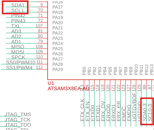
Referring back to my problems with the generic / clone XD-204 shield in my previous post, I had to connect SDA and SCL from the shield to pins 20 & 21 of my Dué using some Dupont jumper wires, and then it worked. But according to Adafruit's latest online resources,

Wiring & Config
As of revision B of the Datalogger shield, we've moved away from using digital pins 10, 11, 12, 13 for SPI and A4, A5 for > I2C. We now use the 2x3 ICSP header, which means that you don't need special customized I2C or SPI libraries to use > with Mega or Leonardo or Zero (or any other future type) of Arduino! [....my assumption being that Dué is included therein]

With that being said, I believed that both the RTC and the SD card functions would be available, and operable from within the same Sketch, using the Rev B Adafruit 1141, without any additional wiring.

I have read through Adafruit's documentation for the 1141 many times but it seems I am still missing some key point. Any help would be appreciated!


Postscript:
I have tried other Examples from the RTClib library with the Adafruit 1440 Datalogger x RTC shield, running on Dué. Here are my pass/fail results:

Interrupts1Hz.ino does NOT work (Compilation error: `` was not declared in this scope)
pcf8253Countdown.ino does NOT work ("Couldn't find RTC")
datecalc.ino this does work, but it seems to be using the host computer's time&date, and NOT the time& date from the RTC (comments????)
pcf8253.ono does NOT work ("Couldn't find RTC")

The dedicated I2C pins (next to AREF) are SDA1 and SCL1, not SDA and SCL. You can look at the schematic of the Due (https://content.arduino.cc/assets/ArduinoDUE_V02g_sch.pdf).

I suspect that that is the root cause of your issue.

If your RTC library supports the use of Wire1, I would try that (without the Dupont cables).

Note:
The latest pinout diagram (https://content.arduino.cc/assets/A000056-full-pinout.pdf) seems to be wrong as it does not match the schematic.

Issue about mismatch between schematic and pinout reported.

The basic Example to test the RTC on my Adafruit 1141 shield is pfc8523.ino
It calls Class RTC_PCF8523 defined within RTClib.h

Within the RTClib.h, that Class does seem to explicitly allow the Wire1 instance. Here are some lines of code snipped from the RTClib.h (lines 406 through 426, inclusive)

class RTC_PCF8523 : RTC_I2C {
public:
  bool begin(TwoWire *wireInstance = &Wire);
  void adjust(const DateTime &dt);
  bool lostPower(void);
  bool initialized(void);
  DateTime now();
  void start(void);
  void stop(void);
  uint8_t isrunning();
  Pcf8523SqwPinMode readSqwPinMode();
  void writeSqwPinMode(Pcf8523SqwPinMode mode);
  void enableSecondTimer(void);
  void disableSecondTimer(void);
  void enableCountdownTimer(PCF8523TimerClockFreq clkFreq, uint8_t numPeriods,
                            uint8_t lowPulseWidth);
  void enableCountdownTimer(PCF8523TimerClockFreq clkFreq, uint8_t numPeriods);
  void disableCountdownTimer(void);
  void deconfigureAllTimers(void);
  void calibrate(Pcf8523OffsetMode mode, int8_t offset);
};

I added #include "Wire.h" to the sketch, pfc8523.ino and modified Line 16 to read,
if (! rtc.begin(&Wire1)) {
which gives me the following Sketch, which Compiles and Uploads without generating any errors. But....it still does not communicate at all: the Serial Monitor does not display any output whatsoever! Helpful hints would be appreciated!

// Date and time functions using a PCF8523 RTC connected via I2C and Wire lib
#include "RTClib.h"
#include "Wire.h"

RTC_PCF8523 rtc;

char daysOfTheWeek[7][12] = {"Sunday", "Monday", "Tuesday", "Wednesday", "Thursday", "Friday", "Saturday"};

void setup () {
  Serial.begin(57600);

#ifndef ESP8266
  while (!Serial); // wait for serial port to connect. Needed for native USB
#endif

  if (! rtc.begin(&Wire1)) {
    Serial.println("Couldn't find RTC");
    Serial.flush();
    while (1) delay(10);
  }

  if (! rtc.initialized() || rtc.lostPower()) {
    Serial.println("RTC is NOT initialized, let's set the time!");
    // When time needs to be set on a new device, or after a power loss, the
    // following line sets the RTC to the date & time this sketch was compiled
    rtc.adjust(DateTime(F(__DATE__), F(__TIME__)));
    // This line sets the RTC with an explicit date & time, for example to set
    // January 21, 2014 at 3am you would call:
    // rtc.adjust(DateTime(2014, 1, 21, 3, 0, 0));
    //
    // Note: allow 2 seconds after inserting battery or applying external power
    // without battery before calling adjust(). This gives the PCF8523's
    // crystal oscillator time to stabilize. If you call adjust() very quickly
    // after the RTC is powered, lostPower() may still return true.
  }

  // When time needs to be re-set on a previously configured device, the
  // following line sets the RTC to the date & time this sketch was compiled
  // rtc.adjust(DateTime(F(__DATE__), F(__TIME__)));
  // This line sets the RTC with an explicit date & time, for example to set
  // January 21, 2014 at 3am you would call:
  // rtc.adjust(DateTime(2014, 1, 21, 3, 0, 0));

  // When the RTC was stopped and stays connected to the battery, it has
  // to be restarted by clearing the STOP bit. Let's do this to ensure
  // the RTC is running.
  rtc.start();

   // The PCF8523 can be calibrated for:
  //        - Aging adjustment
  //        - Temperature compensation
  //        - Accuracy tuning
  // The offset mode to use, once every two hours or once every minute.
  // The offset Offset value from -64 to +63. See the Application Note for calculation of offset values.
  // https://www.nxp.com/docs/en/application-note/AN11247.pdf
  // The deviation in parts per million can be calculated over a period of observation. Both the drift (which can be negative)
  // and the observation period must be in seconds. For accuracy the variation should be observed over about 1 week.
  // Note: any previous calibration should cancelled prior to any new observation period.
  // Example - RTC gaining 43 seconds in 1 week
  float drift = 43; // seconds plus or minus over oservation period - set to 0 to cancel previous calibration.
  float period_sec = (7 * 86400);  // total obsevation period in seconds (86400 = seconds in 1 day:  7 days = (7 * 86400) seconds )
  float deviation_ppm = (drift / period_sec * 1000000); //  deviation in parts per million (μs)
  float drift_unit = 4.34; // use with offset mode PCF8523_TwoHours
  // float drift_unit = 4.069; //For corrections every min the drift_unit is 4.069 ppm (use with offset mode PCF8523_OneMinute)
  int offset = round(deviation_ppm / drift_unit);
  // rtc.calibrate(PCF8523_TwoHours, offset); // Un-comment to perform calibration once drift (seconds) and observation period (seconds) are correct
  // rtc.calibrate(PCF8523_TwoHours, 0); // Un-comment to cancel previous calibration

  Serial.print("Offset is "); Serial.println(offset); // Print to control offset

}

void loop () {
    DateTime now = rtc.now();

    Serial.print(now.year(), DEC);
    Serial.print('/');
    Serial.print(now.month(), DEC);
    Serial.print('/');
    Serial.print(now.day(), DEC);
    Serial.print(" (");
    Serial.print(daysOfTheWeek[now.dayOfTheWeek()]);
    Serial.print(") ");
    Serial.print(now.hour(), DEC);
    Serial.print(':');
    Serial.print(now.minute(), DEC);
    Serial.print(':');
    Serial.print(now.second(), DEC);
    Serial.println();

    Serial.print(" since midnight 1/1/1970 = ");
    Serial.print(now.unixtime());
    Serial.print("s = ");
    Serial.print(now.unixtime() / 86400L);
    Serial.println("d");

    // calculate a date which is 7 days, 12 hours and 30 seconds into the future
    DateTime future (now + TimeSpan(7,12,30,6));

    Serial.print(" now + 7d + 12h + 30m + 6s: ");
    Serial.print(future.year(), DEC);
    Serial.print('/');
    Serial.print(future.month(), DEC);
    Serial.print('/');
    Serial.print(future.day(), DEC);
    Serial.print(' ');
    Serial.print(future.hour(), DEC);
    Serial.print(':');
    Serial.print(future.minute(), DEC);
    Serial.print(':');
    Serial.print(future.second(), DEC);
    Serial.println();

    Serial.println();
    delay(3000);
}

As a test, I bent aside the SCL and SDA pins of the Adafruit shield, then jumpered these two pins to the SDA (Pin 20) and SCL (Pin21) of the Dué. This test confirm that the shield and the Examples work but that the problem is due to communication.

Now, just precisely how to change the code to suit the Dué...

This topic was automatically closed 180 days after the last reply. New replies are no longer allowed.