I need some oversight on this issue I am having. I have a 2.4" display that I am connecting the controller to via SPI, and some of the display's pin need to use GPIO pins of the controller. If I use any other output pin other than the I2C pins the display works, but if I move some wires to use the I2C pins then the display doesn't work. The pins from the display that I am messing around with are the IM0 and IM1 pins on page 5 of the Display Datasheet.
I would prefer to find a way to use the I2C pins as GPIOs since I do not plan on using I2C for this project of mine.
I can show you snippets of where I declare the pins, but I am not allowed to show you the entire code since the project I am working on requires NDA paperwork and acknowledgement.
Below I show you what pins I declare and the void setup:
/************************************************************ DECLARE PINS */
// Pin configuration for your ESP32 Feather
#define TFT_SCLK SCK  // SCLK or CLK
#define TFT_MISO MISO // MISO or SDI
#define TFT_MOSI MOSI // MOSI or SDA
#define TFT_RST 32    // Reset pin, set to -1 if not used
#define TFT_DC 27     // Data/Command select pin
#define TFT_CS SS     // Chip select pin
#define TFT_IM0 22
#define TFT_IM1 20
#define R_LED 13
#define Y_LED 20
#define G_LED 22
#define VBATPIN A13
#define SELECT GPIO_NUM_25 // config for select and bootup
 #define UP 7
// #define UP 8
 #define DOWN 8
// #define DOWN 7

void setup()
{
  pinMode(TFT_CS, OUTPUT);
  pinMode(TFT_DC, OUTPUT);
  pinMode(TFT_RST, OUTPUT);
  pinMode(TFT_IM0, OUTPUT);
  pinMode(TFT_IM1, OUTPUT);
  pinMode(R_LED, OUTPUT);
  pinMode(Y_LED, OUTPUT);
  pinMode(G_LED, OUTPUT);

  digitalWrite(TFT_CS, INPUT_PULLUP);
  digitalWrite(TFT_RST, LOW);
  // IM0-0 IM1-1 = FULL DUPLEX
  // IMO-1 IM1-1 = HALF DUPLEX
  digitalWrite(TFT_IM0, LOW);     // IM0 - 0
  digitalWrite(TFT_IM1, HIGH);    // IM1 - 1
  digitalWrite(R_LED, LOW);
  digitalWrite(Y_LED, LOW);
  digitalWrite(G_LED, LOW);

  Serial.begin(115200);

  maxlipo.begin();
  Serial.print(F("Found MAX17048"));
  Serial.print(F(" with Chip ID: 0x"));
  Serial.println(maxlipo.getChipID(), HEX);

  tft.init(240, 320); // Initialize the display
  tft.fillScreen(ST77XX_BLACK);

  /*
    while (!Serial.available())
    {
    ; // do nothing and wait for key press
    }
  */

  Serial << "Wait for 3 seconds." << endl;

  delay(3000);
}
Good day.
I had used the Lib TFT_eSPI with my Arduino Nano ESP32.
When the Lib is installed then you need to check where the Lib is lokated to your PC. Then you need to adapt two files:
User_Setup.h (less inside User_Setup_Select.h)
In User_Setup define the used pins (GPIO Numbers) and choos the driver for display. In my case it had looked this way.
#define TFT_MISO 47     // MISO
#define TFT_MOSI 38     // In some display driver board, it might be written as "SDA" and so on.
#define TFT_SCLK 21     // Clock
#define TFT_CS   18     // Chip select control pin
#define TFT_DC   17     // Data Command control pin
#define TFT_RST  10     // Reset pin (could connect to Arduino RESET pin)
//#define TFT_BL   22   // LED back-light

#define TOUCH_CS -1     // Chip select pin (T_CS) of touch screen

#define GC9A01_DRIVER // my used display driver.
There is also a define for your driver available:
#define ST7789_DRIVER
And include needed:
#include <TFT_eSPI.h>
I had tried with different pins on the Nano ESP32 and all worked well.
Best regards Mascho
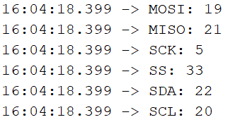
I think they are at GPIO22 (SDA) and GPIO20 (SCL). Also Y_LED and G_LED and TFT_IM0 and TFT_IM1 are at those pins. Those pins are busy pins
Where is the Wire.begin() ?
Hey @Koepel I am trying not to use the I2C bus but use the two pins for the I2C bus as GPIO. It is just strange that it doesn't work directly from default as GPIO. Therefore, I was wondering if anyone has had experience with this board using I2C pins as GPIOs?
GPIO20 and GPIO22 are normal digital pins.
You should be able to use pinMode() and digitalRead() and digitalWrite().
You have "MAX17048" in your sketch, so I assumed that you are using the I2C bus.
Then you have also a TFT_IMO and TFT_IM1 on those pins and leds.
The sketch that you showed does not compile and you use pins 20 and 21 three times and now you want to use them as normal digital input and output pins. So you want to use them 4 times.
You can use a pin only once.
I'm sorry, but it is too vague.
Show a full sketch. Make a schematic that shows all the wiring (you may draw it on a piece of paper with a pen). Make a photo. Ask a good question Then you get a good answer.
@Koepel Why thank you very much for noticing that. I think overlooking and testing multiple things such as LED's and the "MAX17048" made me disregard that I have already declared those pins something else.
That solved me issue. See... it doesn't need a full code and drawing to solve a simple issue like this. I just needed a second set of eyes to take the time to look at my declarations from the code I posted.