ADC sampling rate Timer counter trigger with DMA not correct

hello Mrs ,
i m working on ADC sampling with Arduino due , the ADC is triggered with TC at 13.2khz
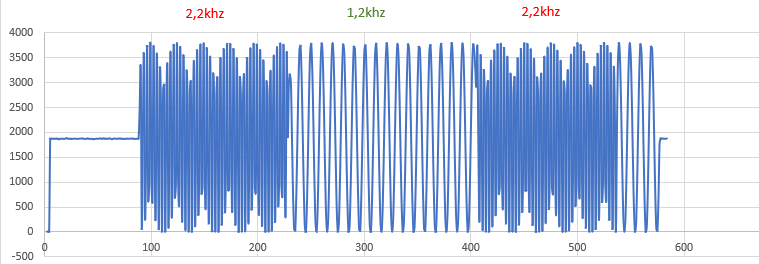
the audio signal to be sampled at A0 is an FSK signal with f1=1.2khz and f2=2.2khz , i need to recover samples in the main loop to process them , but received sample from serial port are not correctly sampled (i dont obtein my sent signal) ,
the signal apear like aliasing (the ADC samples at lower frequency than 13.2khz ) but i dont know why ?? here is the code :any help please slight_smile:

the code is :volatile int bufn,obufn;
uint16_t buf[2][1024]; // 4 buffers of 256 readings

void ADC_Handler(){

int f=ADC->ADC_ISR;
if (f&(1<<27)){
bufn=(bufn+1)&1;

ADC->ADC_RNPR=(uint32_t)buf[bufn];

ADC->ADC_RNCR=1024;
}
}
//
void setup() {
//
Serial.begin(19200);
pmc_enable_periph_clk (TC_INTERFACE_ID + 0*3+0) ; // clock the TC0 channel 0

TcChannel * t = &(TC0->TC_CHANNEL)[0] ; // pointer to TC0 registers for its channel 0
t->TC_CCR = TC_CCR_CLKDIS ; // disable internal clocking while setup regs
t->TC_IDR = 0xFFFFFFFF ; // disable interrupts
t->TC_SR ; // read int status reg to clear pending
t->TC_CMR = TC_CMR_TCCLKS_TIMER_CLOCK1 | // use TCLK1 (prescale by 2, = 42MHz)
TC_CMR_WAVE | // waveform mode
TC_CMR_WAVSEL_UP_RC | // count-up PWM using RC as threshold
TC_CMR_EEVT_XC0 | // Set external events from XC0 (this setup TIOB as output)
TC_CMR_ACPA_CLEAR | TC_CMR_ACPC_CLEAR |
TC_CMR_BCPB_CLEAR | TC_CMR_BCPC_CLEAR ;

t->TC_RC = 3182 ; // counter resets on RC, so sets period in terms of13200hz
t->TC_RA = 1591 ; // roughly square wave
t->TC_CMR = (t->TC_CMR & 0xFFF0FFFF) | TC_CMR_ACPA_CLEAR | TC_CMR_ACPC_SET ; // set clear and set from RA and RC compares
t->TC_CCR = TC_CCR_CLKEN | TC_CCR_SWTRG ; // re-enable local clocking and switch to hardware trigger source.

NVIC_EnableIRQ(ADC_IRQn);
ADC->ADC_CHDR = 0xFFFF ; // disable all channels
ADC->ADC_CHER = 0x80 ; // enable just A0
ADC->ADC_CGR = 0x15555555 ; // All gains set to x1
ADC->ADC_COR = 0x00000000 ; // All offsets off
ADC->ADC_MR = (ADC->ADC_MR & 0xFFFFFFF0)| (1 << 1) | ADC_MR_TRGEN; // 1 = trig source TIO from TC0

ADC->ADC_IDR=~(1<<27);
ADC->ADC_IER=1<<27;

ADC->ADC_RPR=(uint32_t)buf[0]; // DMA buffer
ADC->ADC_RCR=1024;
ADC->ADC_RNPR=(uint32_t)buf[1]; // next DMA buffer
ADC->ADC_RNCR=1024;

bufn=1;
obufn=0;

ADC->ADC_PTCR |= ADC_PTCR_RXTEN; // Enable PDC Receiver channel request
ADC->ADC_CR = ADC_CR_START;
//
}
//
void loop(){
while((obufn + 1)%2==bufn);// wait for buffer to be full
obufn=(obufn+1)&1;
Serial.println(*buf[obufn]); // send it
}


here the signal obteined in serial port ,(sinusoide of 1.2khz and 2.2k are not correctly sampled

Hi, without analyzing your sketch in detail, I see that you are printing ADC values with 19200 baud. One value can be 4 digits + CR + LF, i.e. 6 characters.
The repetition rate of printing therefore is 19200/6 = 3200 Hz!
But you want to print values generated with 13200 Hz.
Use a higher baud rate, e.g. 115000 baud (>13200*6).

thinks for the reply , i have tried higher baud rate (115200) but the result remain the same as given in previous figure , i suspect the problem is not in relation with baud rate !!

what I don’t understand is that when i change size of DMA buffers ( 2048 instead 1024) the aspect of received signal change compared to the previous figure , in my inderstanding buffer is just for buffering , What changes the signal aspect then?

Do you find documentation that says DMA is "synchronized" with anything? You may be triggering it, but that does not mean it is actually done at the instance. Does the DMA control return a completed signal that you can test?

At first, I'm not familiar with ADC and DMA register programming. Therefore I don't understand in detail what your sketch is doing.

But generally, after triggering ADC by Timer it takes some time until a valid converted value is available. DMA needs to wait until a valid result is available and then transfer it into the buffer array.
I guess Paul_KD7HBs "synchronized" comment points to this problem.

For sure, ADC is providing a flag or something like that when a conversion is complete. DMA has to synch on this flag.
Are you sure that your sketch is considering this?

hello , i did some investigation , and the problem is the output of buffers in the loop , i have tried this in the main loop
for(int i=0; i<256;i++)
{
Serial.println(buf[obufn][i]);

the samples are correctly sampled , so, is their any prposition to output the DMA buffers continousely without the for loop ????
}

DMA has always been and will always be a separate processor connected to the main processor. Identical to sending a message to a different Arduino board and waiting for a reply.
The advantage of DMA is your program can do other things while waiting for the DMA processor to complete the job it has been given.
Yes, it takes a whole different type of program logic to take advantage of DMA. Your program cannot buffer data faster than it can be removed using DMA.

Do you expect that your print statement

will print 256 values?

The for loop of course is printing 256 values, but
Serial.println(*buf[obufn]);
is printing only one value.