Hi, I am currently building a 737 overhead with two Arduinos and multiplexors. Currently I only have a lot of switches and 12 LEDs connected. I am in the early stage and only hooked up the LEDS at a test to check things were working as they should but I won't be adding anymore LED's until I get external power. My question is regarding adding the external power and how do I introduce the PSU into the circuit. I have attached a (very childlike ..sorry) circuit diagram of how it is currently connected and the way I would put the PSU. I am not 100% on whether this is how it needs to be. Also I have simplified the amount that is connected but the rest of the switches, LEDs and multiplexors would be a rinse and repeat of what's in the diagram with multiplexors split between both arduinos. Also there will be not just one long chain of daisy chained grounds, they will come into the ground bus from probably each panel or two if it's a smaller panel. Can you have a look over this and see if and where I am going wrong and if my solution for the PSU is correct. Currently everything is working as it should. My main concern is the power requirements as I add the LED's. I am using mobiflight to program the switches etc.
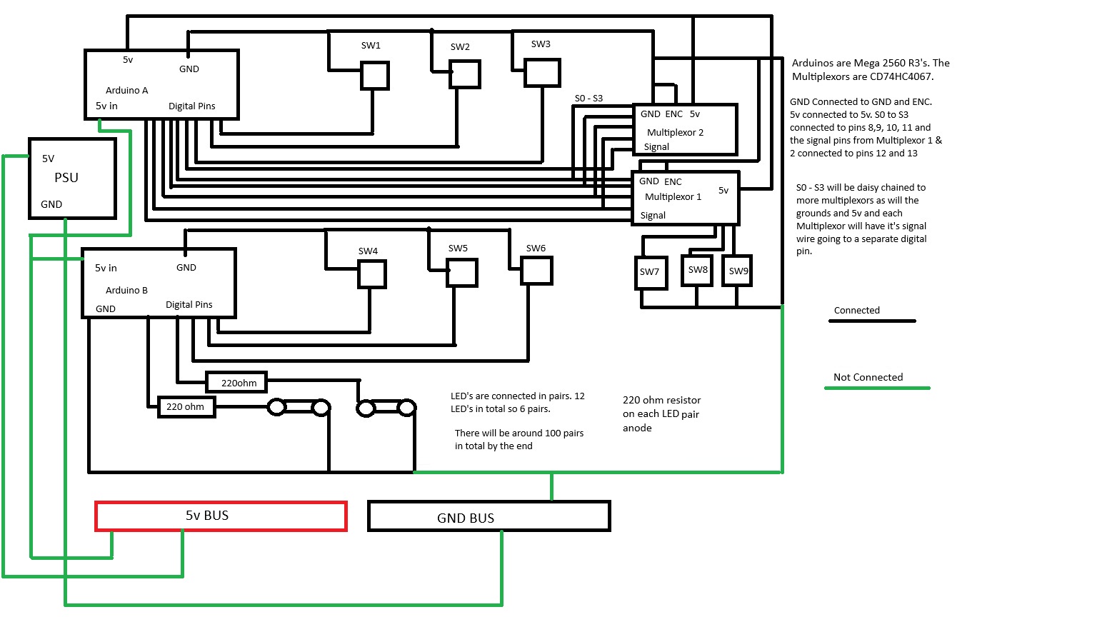
You have connected your PSU to a 5V and GND distribution bar(s): that is exactly right.
What is your 5V supply rated for? How many amps? What is the expected current draw from the total circuit once complete? Add up the current draw from all the devices (LEDs, Arduinos, anything else) at maximum load and subtract that sum from the rated current capability of the supply.
If your supply is less than 1.5 times (minimum) the sum of all the devices drawing current, it's too low.
What is your power supply, specifically?
I would use 'normal' wall warts for the two arduino's. The PSU may get noise introduced, and it may if not sized properly suffer dips, that is why I always power the MCU's individually.
I was looking at getting either something like a 10a or 20a meanwell PSU but I'm also thinking a wall PSU might suffice and be easier to work with. I will be using approximately 2 Arduinos, 200 LED's, 10 Multiplexors, 5 on each Arduino and at some point a 3 line LCD display and 2 7 segment LED displays. I calculated at 20ma per LED, 50ma for the Arduinos and multiplexors. 40ma for the segments and 60 for the LCD display. I don't know if my maths are correct but I worked that out at just under 5 amps but I could be wrong.
I was looking at these PSUs.
or
That was one of the options I was considering. See post above.
So one of those 10A for the LEDs, and two wall warts, one for each arduino?
On your diagram, I do NOT see the separate power for the LED's.
Do you understand that a single pin on a Mega 2560 Rev3 is limited to 20mA? Those pins are meant to be used for logic not power.
What you need is 3 or 4 power supplies.
For each 2560, a wall power adapter of sufficient power for JUST the 2560. See the following for details.
1 large or 2 medium I would use 2) to power all the stuff you want to control.
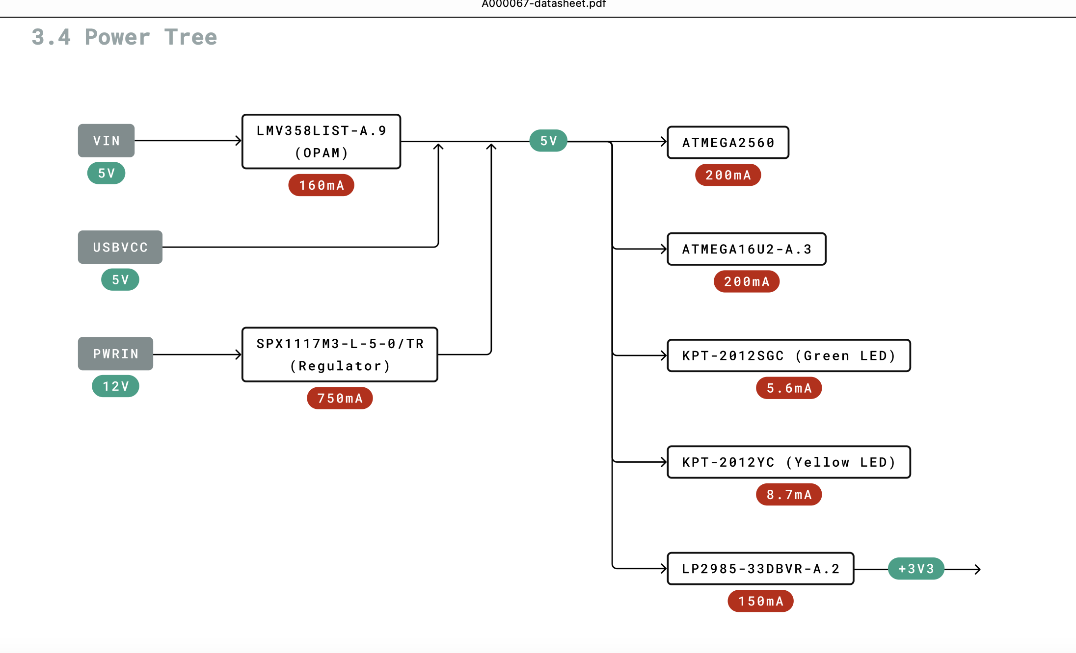
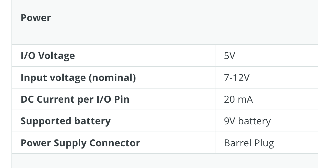
READ the datasheet. Here are some excerpts.
Here is ChatGPT's responses to the question
How much power does an Arduino Mega 2560 Rev3 need in order to power ALL pins at maximum
The Arduino Mega 2560 Rev3 has specific power requirements depending on the total current drawn by the connected devices. Here’s a breakdown:
Key Electrical Specifications:
- Input Voltage Range:
• USB: 5V.
• Barrel Jack: 7V to 12V (recommended), with a safe range of 6V to 20V.
- Pin Current Limits:
• Total Current for I/O Pins: Maximum 200 mA.
• Individual I/O Pin: 40 mA (absolute maximum; recommended: 20 mA per pin for safety).
- Power Regulator Limits:
• The on-board voltage regulator can supply around 500 mA when powered via the barrel jack or Vin. However, higher loads can cause overheating or instability.
• USB can provide up to 500 mA, shared between the Arduino and connected peripherals.
Power Calculation:
To power all pins at their theoretical maximum:
• Digital I/O Pins (54 total):
• If each pin sources 40 mA, that’s 54 × 40 mA = 2160 mA (2.16 A). However, this far exceeds the 200 mA total I/O current limit.
• Practically, you can use around 20 mA per pin, giving a total of 54 × 20 mA = 1080 mA (1.08 A).
• Analog Pins (16 total):
• If used as digital outputs, they follow the same current rules.
• Power Pins:
• The 5V and 3.3V pins can supply power to external devices, but their current is limited:
• 5V Pin: Around 400–450 mA after powering the Arduino itself (USB-powered).
• 3.3V Pin: Maximum 50 mA.
Total Power Estimate:
At 5V, if all I/O pins are sourcing around 200 mA (safe total) and peripherals draw an additional 100–200 mA, the board could need 500–700 mA.
However, external power supplies (e.g., through a separate 5V regulator) are needed for high-power configurations, as the Arduino cannot supply several amps on its own.
Recommendation:
• If driving high loads (e.g., LEDs, motors, sensors), use external power sources and transistors or relays to handle current beyond the Arduino’s capacity.
• Use a power supply rated for at least 1–2 A if powering many peripherals.
Hi, I was planning to use a 5v PSU rated at at least 10amps. So how would I bring the 5v to each of the LED's and still control the logic from the digital pin.
Did you read the specs?
Did you understand each pin is ONLY capable of 20mA in reality although they are rated 40mA.
How much does each LED consume? Divide 20ma by the LED mA and that is how many LED's you can have per pin.
Perhaps if you produced a proper schematic we could quickly calculate.
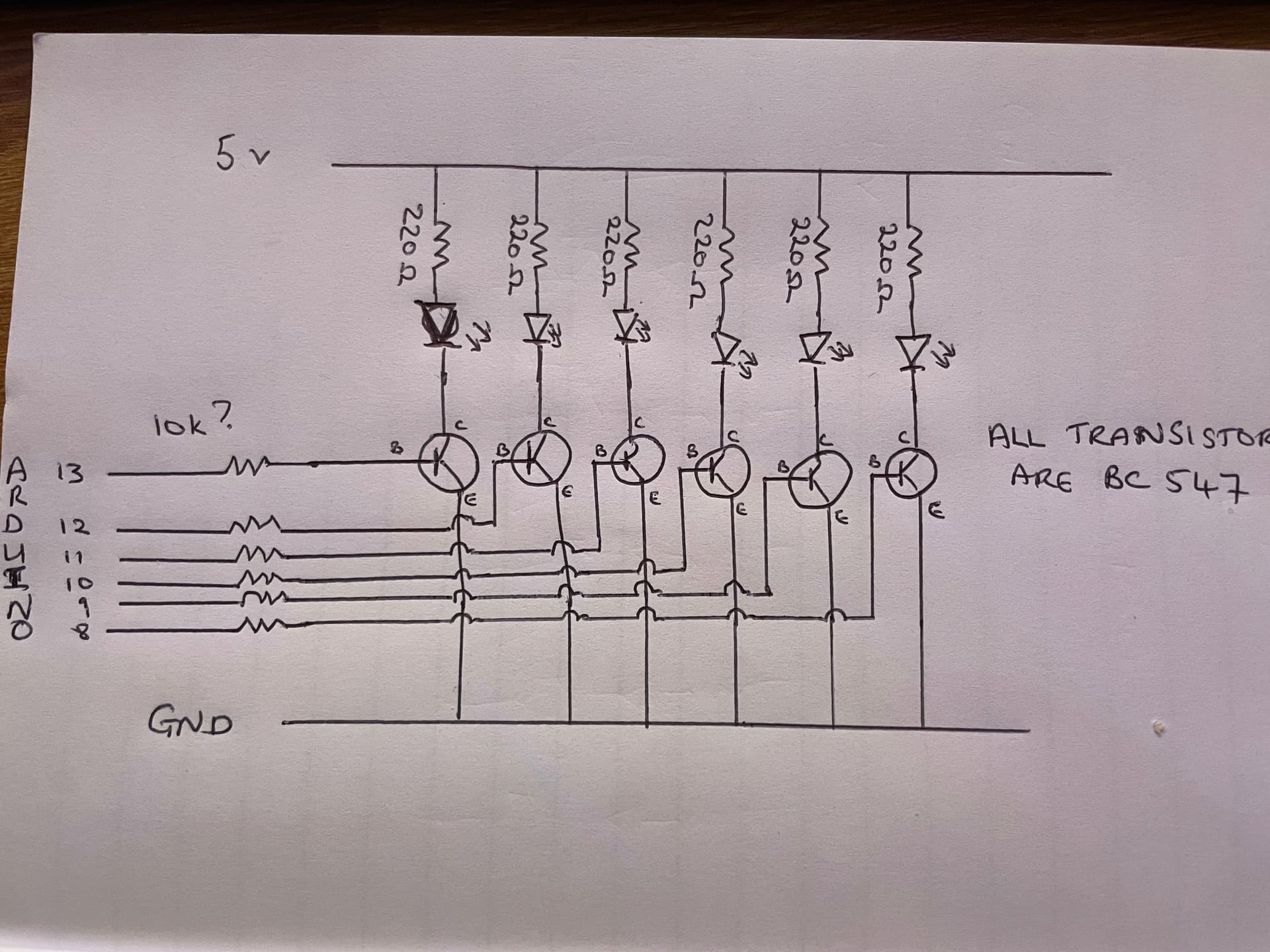
I am relatively new to this, so excuse my slowness. I do understand what you are saying about the power requirement which is why I am here trying to figure this stuff out. So I have went away and looked a little more. Would I be better to use the pins from the Arduino to a transistor to switch on the power for the LED's rather than hooking the LED's up directly. You asked for a circuit diagram so hopefully this hand drawn monstrosity will be closer to what you require. I have removed the other nonsense because I am basically concentrating on the LED's. As I said I have over 100 LED's to power. What I didn't show in the diagram is that the LED's are in pairs with each LED's anode and cathode connected. Also not sure if the selection of transistor is sufficient or the resistors between the Arduino pins are the correct size or even if they are required. As I said I am new to this but I am trying to learn although that doesn't happen at as quick a pace as it did in my younger days.
Hi,
That looks fine, the 10K base resistors will work, but 1K would ensure the BC547's were fully saturated when switched on.
220R will give about 15mA LED current, which should be good.
Tom.. ![]()
![]()
![]()
![]()
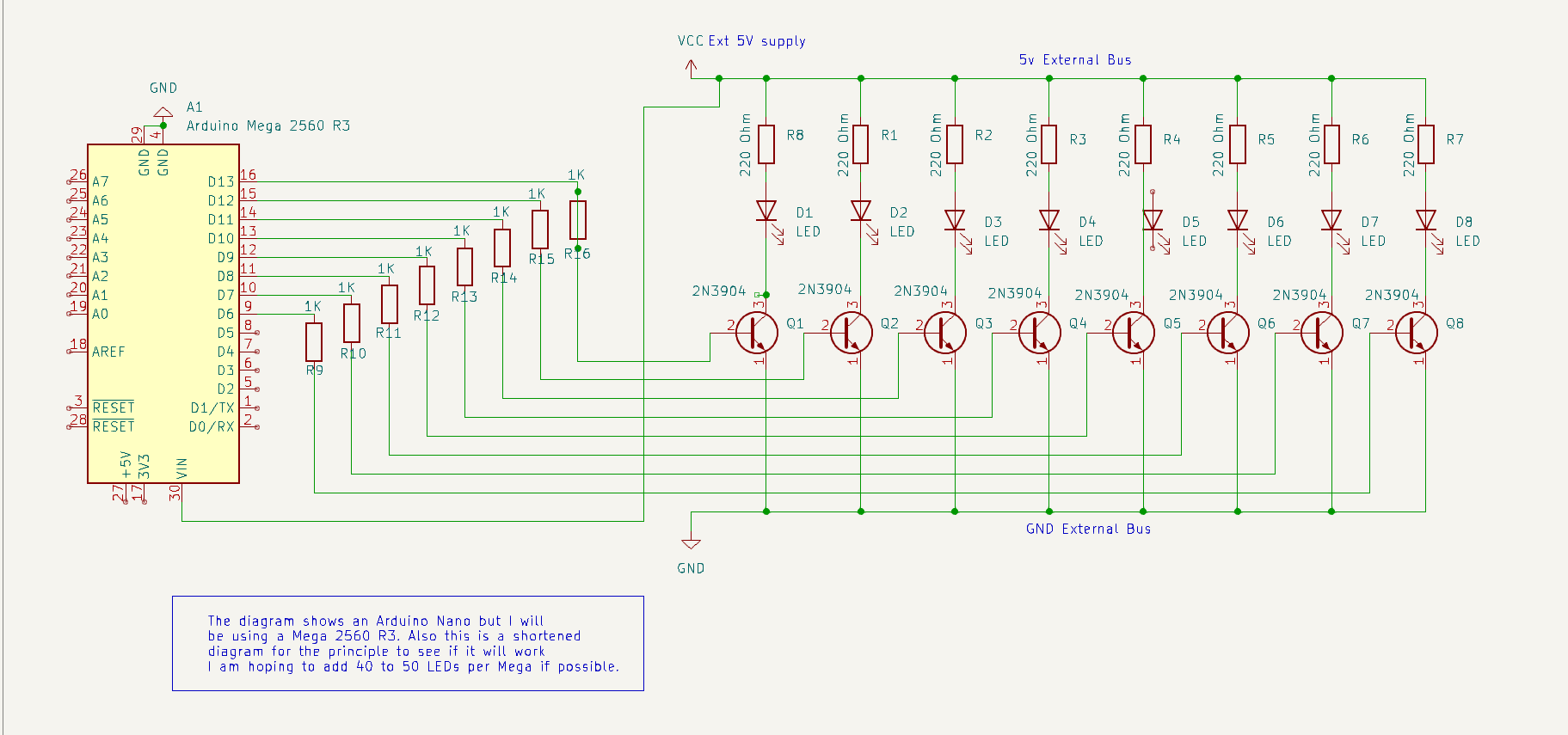
Thank you, I finally figured Kicad out (mostly) so I done a circuit diagram. The transistor is different, not exactly sure on the best one to go for to be honest, any suggestions. However I will change the resistor to 1K as per your suggestion.
Also, will this method allow me to connect multiple LED's ie, 40 or 50 to one Arduino (it's a Mega not a nano as shown) or will I still be limited.
Missed the mega comment
One arduino does not have 40-50 pins.
LED is parallel don't always work. One may never come on or the brightness between the two may be quite noticeable.
You may consider using one of these ICs, may make life much easier:
TLC5916
TPIC6C596
TPIC6B595
MIC5819
The TLC5916 is nice since it only requires 1 resistor for 8 LED.
Don't know if IC's are a bit out of my capability. I'm using Mobiflight as the software to program everything so I have no idea of coding these things. Each LED pair goes to a different annunciator and each annunciator requires it's own pin. I tried this circuit but I'll wager it is completely wrong. I'm sure the transistors should probably be removed as well as a complete rewire.

I'm not familiar with the Mobiflight software so I don't know if it will work with shift register type LED drivers. If you don'r know how to modify it to use the TLC5916, then maybe you should ignore my suggection.
I'm pretty sure it does, not sure to what extent though, I know of one board that includes both multiplexors and shift registers

Failing that, do you see any issues with my original schematic (updated a little) and will it allow me to use multiple LED's on the Arduino i.e 40 to 50 as I will be powering the LED's themselves with an external PSU.
One more option that will make things simpler, the TBD62783. It's basically an array of 8 MOSFETs in a single 18 pin IC package.
Input resistors are not necessary so you only need the current limiting resistors for each LED.
You connect the LED and resistor between the output and Ground.
Basically it save you from having to use 8 seperate transistors with base resistors.
You can use as many as you need. You can also put 2 LEDs in series on each output as long as Vcc is greater than 2 x the max Forward voltage (Vf) for the LEDs. For example if the max Vf of the LEDs is 3V than Vcc should be greater than 6V
If can use the TCL5916, then the transistors and LED current limiting resistors are not needed.
The LED just connects directly to the TLC output