Adding LDR to sketch

Hello .Still pretty new to all of this but I am learning Question of the day is this .
when running the following sketch I can activate my original sketch by shading or covering the LDR.
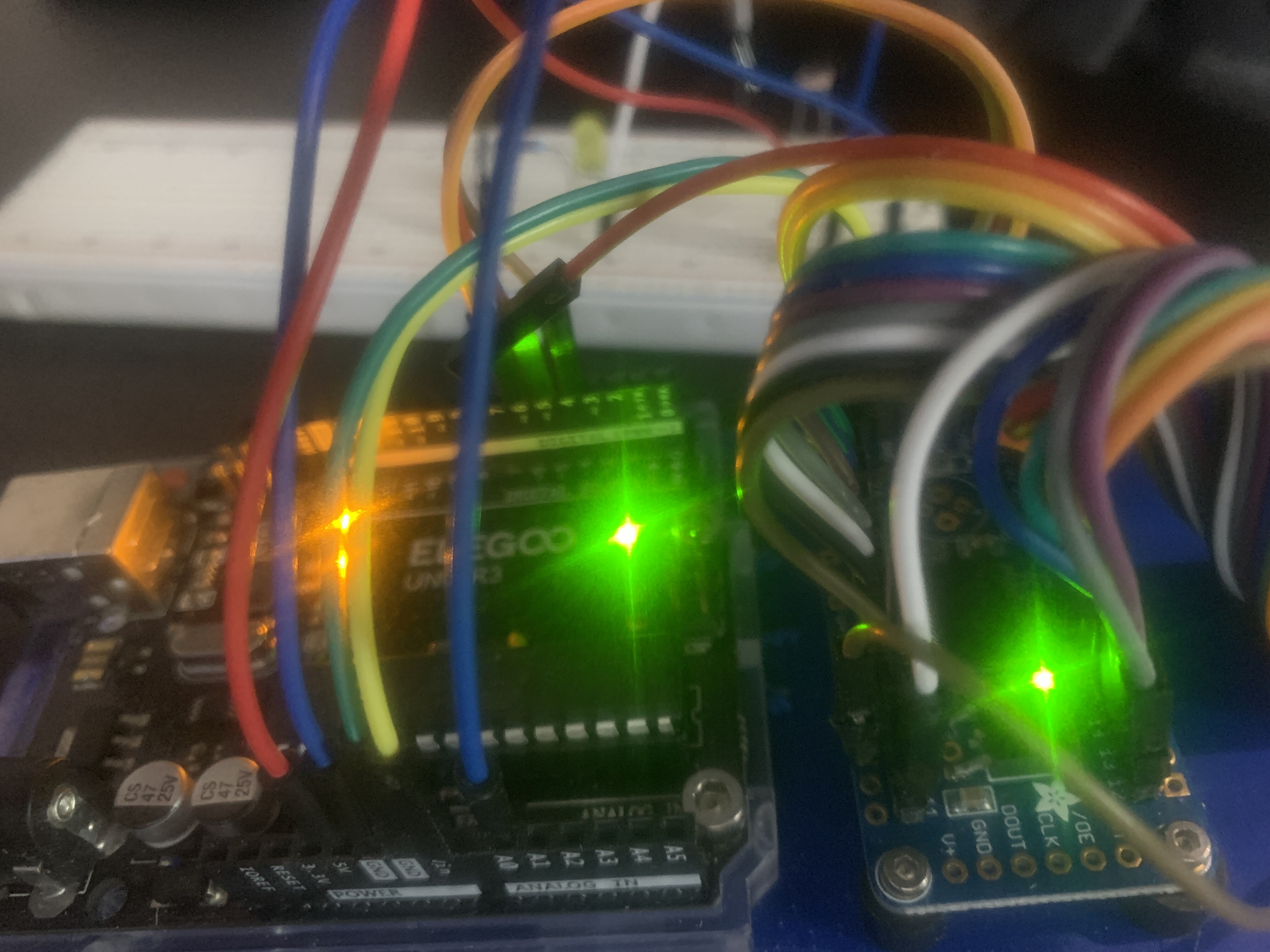
The sketch starts . When I uncover the LDR the sketch stops but one lone LED remains lit
Haven't figured that part out yet .
For what it's worth I eventually wish to use a timer so that the sketch only runs for lets say 4 hours and then stops until triggered the next evening
PS Hope I posted the code proper this time

#include "Adafruit_TLC5947.h"
// How many boards do you have chained?

#define NUM_TLC5947 1
#define data 4
#define clock 5
#define latch 6
#define oe -1  // set to -1 to not use the enable pin (its optional)
#define BRIGHT 4095
#define PRETTY_BRIGHT 700
#define DIM 100
#define OFF 0
#define NUM_LEDS 20
#define Threshold_light 400
#define Threshold_dark 200
int LDRpin(A0);
int LDRValue = 0;

Adafruit_TLC5947 tlc = Adafruit_TLC5947(NUM_TLC5947, clock, data, latch);


void setup() {

  Serial.begin(9600);

  LDRValue = analogRead(LDRpin);
  pinMode(LDRpin, INPUT);


  Serial.println("TLC5947 test");
  tlc.begin();
  if (oe >= 0) {
    pinMode(oe, OUTPUT);
    digitalWrite(oe, LOW);
  }
}

void loop() {


  LDRValue = analogRead(LDRpin);
  Serial.println(LDRValue);
  delay(2);
  if (LDRValue <= 200) {


    int i;
    uint16_t led_value;
    for (int i = 0; i < NUM_LEDS; i++) {
      tlc.setPWM(i, BRIGHT);
      tlc.setPWM((i + NUM_LEDS - 3) % NUM_LEDS, 0);
      tlc.setPWM((i + NUM_LEDS - 2) % NUM_LEDS, DIM);
      tlc.setPWM((i + NUM_LEDS - 1) % NUM_LEDS, PRETTY_BRIGHT);
      tlc.setPWM((i + NUM_LEDS + 1) % NUM_LEDS, PRETTY_BRIGHT);
      tlc.setPWM((i + NUM_LEDS + 2) % NUM_LEDS, DIM);
      tlc.setPWM((i + NUM_LEDS + 3) % NUM_LEDS, 0);
      tlc.write();
      delay(100);
    }
  } else {
    (LDRValue >= Threshold_light);
    {
      void stop();
    }
  }
}

int LDRpin(A0);

Change to:

const byte LDRpin = A0;

those lines were failed attempts . I left them there so you could see what I've been trying

I will try this . The bottom one looks familiar where I was trying to pick apart another sketch

The final result is no different . when sensing daylight the LEDS ( which blink in a sequential pattern around a disc ) all stop except one LED stays lit.. Actually it may be 3 . ONE BRIGHT, ONE PRETTY BRIGHT and ONE DIM They're very close together in a white PLA ring which doesn't do much to block light from the LED beside it

Sorry but also no change

Show us your current sketch.


Always show us a good schematic of your proposed circuit.
Show us good images of your ‘actual’ wiring.
Give links to components.

#include "Adafruit_TLC5947.h"
// How many boards do you have chained?

#define NUM_TLC5947 1
#define data 4
#define clock 5
#define latch 6
#define oe -1  // set to -1 to not use the enable pin (its optional)
#define BRIGHT 4095
#define PRETTY_BRIGHT 700
#define DIM 100
#define OFF 0
#define NUM_LEDS 20
#define Threshold_light 400
#define Threshold_dark 200
const byte LDRpin = A0;
int LDRValue = 0;

Adafruit_TLC5947 tlc = Adafruit_TLC5947(NUM_TLC5947, clock, data, latch);


void setup() {

  Serial.begin(9600);

  LDRValue = analogRead(LDRpin);
  pinMode(LDRpin, INPUT);


  Serial.println("TLC5947 test");
  tlc.begin();
  if (oe >= 0) {
    pinMode(oe, OUTPUT);
    digitalWrite(oe, LOW);
  }
}

void loop() {

  LDRValue = analogRead(LDRpin);
  Serial.println(LDRValue);
  delay(2);
  if (LDRValue <= 200) {

    for (int i = 0; i < NUM_LEDS; i++) {
      tlc.setPWM(i, BRIGHT);
      tlc.setPWM((i + NUM_LEDS - 3) % NUM_LEDS, 0);
      tlc.setPWM((i + NUM_LEDS - 2) % NUM_LEDS, DIM);
      tlc.setPWM((i + NUM_LEDS - 1) % NUM_LEDS, PRETTY_BRIGHT);
      tlc.setPWM((i + NUM_LEDS + 1) % NUM_LEDS, PRETTY_BRIGHT);
      tlc.setPWM((i + NUM_LEDS + 2) % NUM_LEDS, DIM);
      tlc.setPWM((i + NUM_LEDS + 3) % NUM_LEDS, 0);
      tlc.write();
      delay(100);
    }
  } else {
    
       // this calls the stop function we created. 
      stop();
    
  }
}

/// This creates a new function called stop()
void stop() {
  for (int i = 0; i < NUM_LEDS; i++) {
    tlc.setPWM(i, 0);
  }
}

I was trying to find something like clear all LEDS if sensing daylight but I'm pretty new to this .
I also tried ( but only once) to install the universal timer library, wondering if a timer would stop all the lights .
Haven't got the timer 100% figured out yet . Got frustrated and came here hoping someone could solve in 5 mins what I've been at for a couple of days

Tried to upload a picture from my phone but I'm not sure how...sorry

On (my) phone, the image upload (arrow pointing up from a box) is located on the lower right, below the reply box.


Don't know if these pics help much ..Rest assured that covering and uncovering the LDR has the desired effect except for leaving the last lights on

You could make a timer using the millis(); function to automatically turn off the LEDS...

  1. Define a constant that holds the number of millis you want (for this example, 4 hours.
unsigned long TURN_OFF_ALL_LEDS = 1000 * 60 * 60 * 4; // ms/sec * sec/min * min/hr * 4 hours
  1. Create a variable to know what the millis(); clock value at the time you turn the LEDS ON.
unsigned long currentMillis;
  1. Near the end of setup();, set currentMillis to the millis(); clock value
  currentMillis = millis();
  1. After you make your LEDs turn on, monitor currentMillis for a value larger than 4 hours (in milliseconds), and if that occurs, turn off all LEDS.
  if (currentMillis > TURN_OFF_ALL_LEDS) {
    stop();
  }
1 Like

#define oe -1  // set to -1 to not use the enable pin (its optional)

  if (oe >= 0) {
    pinMode(oe, OUTPUT);
    digitalWrite(oe, LOW);
  • The result will be oe = high Z.

  • you want oe to be LOW to enable the board, at high Z it is disabled

Draw us a hand made schematic.

Can you print the value of the LDR at analog pin ... Serial.println(analogRead(LDR_PIN));... the pin might have a value.

I will try this for a much shorter tie frame of a few minutes to see if t works .
Question will this still allow everything to reset and start again the next night?

The stop() function is only setting the LEDs to zero. The loop() continues f.o.r.e.v.e.r.

I like the sound of this and will try it since the timer function is the eventual desired plan.
This is for a battery operated and solar charged outdoor project Thus the reason for a timer to not run down the battery Summer use only since snow would not be good for this but I'd love to get this part working right soon and do my build thru the winter
Since I've never written this kind of code or much of anything it'll probably take me hours ...lol

I did use the serial monitor to get my values . 200or less is really dark.300 and higher is ambient room light