I have found quite a few posts on this topic in my searches but all of them seem to fizzle out before a resolution was found.
I have a resistive foil heating element that has about 28ohms of resistance. I would like to use a mosfet like an IRLZ34N or an IRLB8721 (or whatever someone suggests), an Arduino Uno, and a 12vdc power supply to control the amount of heat the foil heating element generates.
In the code, I will do an analogwrite to the appropriate pin to the mosfet, and I don't need that value to change dynamically (I don't need it regulated/adjusted based on a temp sensor input for example). When I change the value, it will be manually via sketch upload with a new hard-coded value in it. It will be very infrequent, but I do need the ability to do it.
I found the post linked below and have implemented just the heater control portion of the circuit, and in the sketch I simply perform an analogwrite with a single value. I am using the same 10k resistor and same IRLZ34N mosfet. I have it "working" but the heating output is strange. Ideally the heat the foil heater generates would go up from 0 to 255, and while it generally does that, it seems to go up and down as you go up. IE sending a value of 100 would result in a small amount of warmth. Sending a value of 105 would feel like it's off. Sending a value of 110 would be hot. Maybe the mosfet I'm using or the resistor I'm pairing it with isn't right?
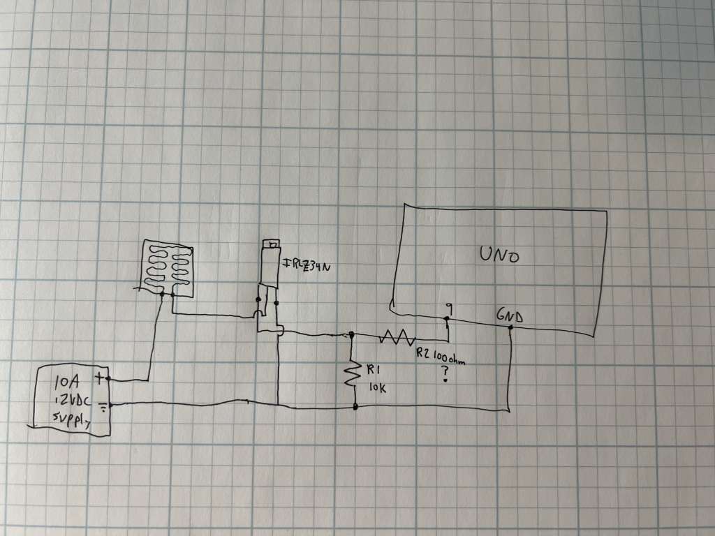
I hate Fritzing diagrams, but at least this one is simple enough to be readable. I would have a 100 ohm resistor in series with the Gate drive to the FET, but otherwise the circuit looks correct. Are you sure that your power supply can provide the current you need? If you connect the element directly to the supply without anything else and leave it for five minutes, is it still hot?
Thank you very much for the reply - Should I remove the 10k resistor when I add the 100ohm resistor, or should I simply add a 100ohm resistor in series while keeping the 10k resistor in place as it is now?
I went to the link you indicated and noticed an inconsistency.
The author uses a UNO and pin A5 (digital 19) as an output to control the MOSFET.
In the code he defines this pin with the name: #define Heater_PIN A5
and in the code he uses: analogWrite(Heater_PIN, outputVal);
analogWrite is a PWM instruction, but pin A5 is not a PWM pin.
The PWM pins of the Arduino UNO are pins 3, 5, 6, 9, 10 and 11.
Which pin are you using for your PWM?
To make it easier for us to help, I suggest that you post your code and a schematic of your project.
This schematic can be done freehand and photographed and then post the image.
You can keep the 10k. It's a "safety" that avoids the gate floating if the arduino is disconnected. A floating gate could cause the FET to enter the active region where it may dissipate a lot of heat.
However, note that the 10k should be connected to the Arduino end of the 100ohm, not the FET end.
@ruilviana that was it! Good catch! Once I put it on an actual analog pin, the temperature vs pin write value began working as expected. Thank you so much for catching that. Can't believe I didn't notice it. I was so consumed with this being a resistor/fet issue that I didn't even focus on that.
Here is my code, all hard coded just for clarity. This is really all I need to do in terms of heater control. Every week or two I may update the output value to tweak the power to the heater and will simply recompile and re-upload.
void setup() {
pinMode(9,OUTPUT);
Serial.begin(9600);
analogWrite(9, 50);
}