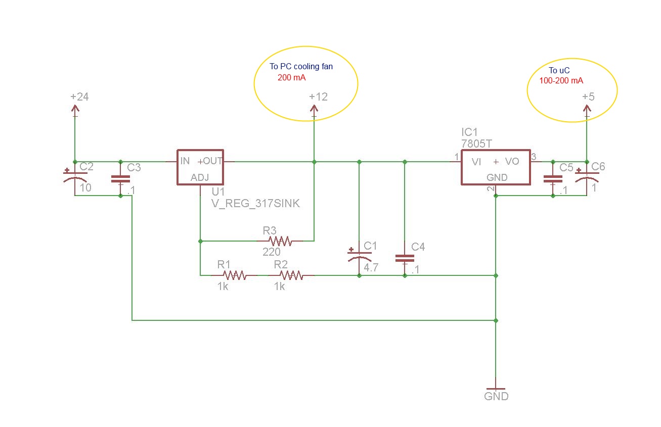
I have built this voltage regulator circuit based on LM317 and LM7805 ic's, and wonder if someone could take a look to see if it is acceptable. More specifically, I am a bit confused on the calcs to determine if the load on the voltage regulators is within spec, or will lead to shortened life due to overheating.
As I have been using this circuit, I note that the Lm317 gets noticeably warm, however the 7805 does not. I am aware that these linear regulators are typically quite inefficient when the supply voltage is substantially higher than the output, essentially burning off the difference in heat. However I am deriving the 24v from mains power and can live with the lack of efficiency.
I do have an aluminum heatsink attached to the 317 and the cooling fan is blowing directly on it.
All of the current is passing through the LM317. You are "dropping" 12V across the LM317 and passing about 400mA through it. That's 4.8 Watts.
The LM7805 is dropping 7V at 200mA = 1.4 Watts.
If you connect the LM7805 directly to 24V, it will drop 19V at 200mA = 3.8 Watts, and the LM317 will be dissipating 2.4W.
I am a bit confused on the calcs to determine if the load on the voltage regulators is within spec
Heat dissipation calculations can be tricky, and I think the best thing is to measure the case temperature of the device to make sure it's withing temperature spec. And remember, you are getting a temperature rise above ambient. If the room/environmental temperature goes up by 10 degrees, the device temperature will also go up 10 degrees.
There's a rule-of-thumb that if you can hold your finger on it, it's OK. If not, the part might be too hot.
DVDdoug:
Heat dissipation calculations can be tricky,
Tell me about it:)
DVDdoug:
and I think the best thing is to measure the case temperature of the device to make sure it's withing temperature spec.
There's a rule-of-thumb that if you can hold your finger on it, it's OK. If not, the part might be too hot
Not sure exactly where is the point at which to measure temp...would pointing an ir temp gun at the middle of the heatsink be sufficient, or should the "case" temp be measured elsewhere?
I can hold my hand on the heatsink indefinitely, so it sounds like I'm safe, but it is quite warm.
Thank you for the useful info about the power dissipation.
Remember it is the junction temperature that is important. You may have a big heatsink but if it is not thermally bonded, the junction can over heat. Make sure you use heatsink paste.
[annoying mode]
You are allowed to use more than one ground symbol on your schematics. It makes it a lot simpler without lots of horizontal lines scurrying back to the central ground.
[/annoying mode]
The only thing I see missing from this is reverse polarity protection diodes. You should protect from the battery being plugged in backwards. No matter how careful you think you are, you will get it wrong one day. Maybe add a fuse to the circuit too.
You also need to protect the regulators from being driven in reverse - if the supply is cut off but C1, C4, C5 and C6 are still charged, they will try to discharge back through the regulators. Add another diode around each regulator which will conduct in this situation.
Unless you somehow need to regulate your fans, it is overkill to use a regulator. Two 12v fans in series can run off the raw 24v input. Is there any reason why this has to be 24v or can you use transformer taps that give you 12v directly?