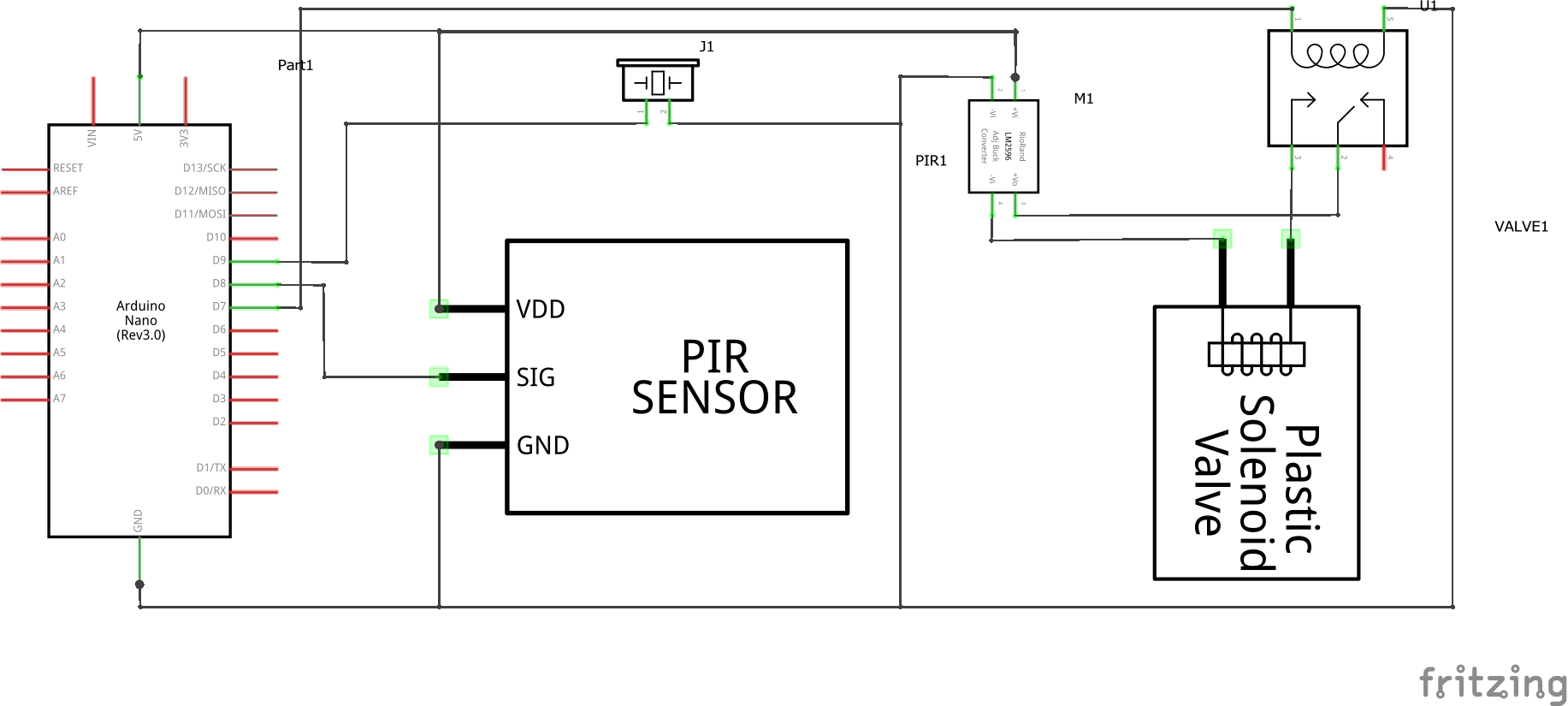
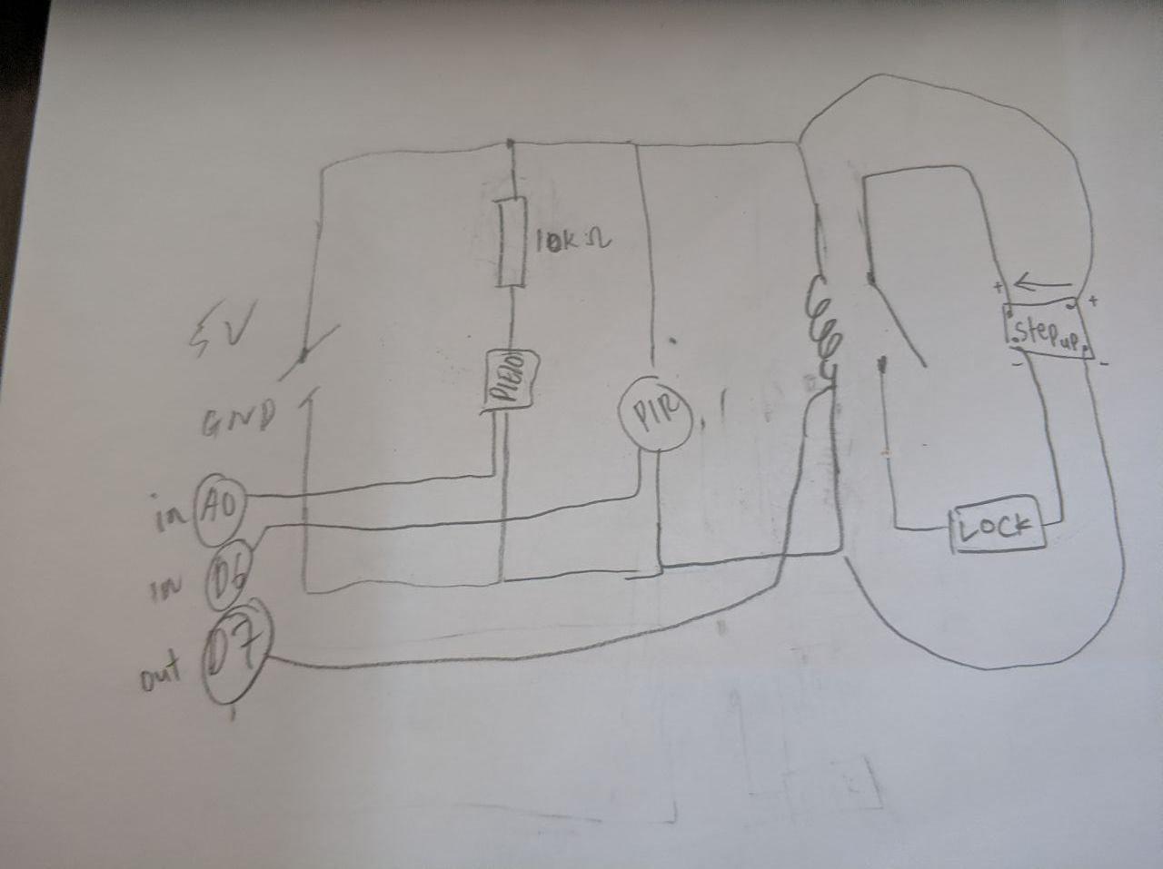
I'm planning to do door lock by knock sensor ( from outside) and PIR motion sensor (from inside).The problem arises as I dont have any extra power source to power up the 12V lock so I try to use step-up module and do something like this:
Parts:
XL6009 DC-DC 4A Step-Up
PIR Motion Sensor HC-SR501
Piezo Electric Disc
5V 1 Channel Relay Board Module
12V Selenoid
Your diagram is difficult to read it follows no conventions, uses undefined abbreviations and gives no clue as to the software used.
Please elaborate: What step-up module, what are the other components (please provide data sheets or a link to the item), and some code that illustrates how you use the signals would be good.
Thanks.
nzmiii:
I'm planning to do door lock by knock sensor ( from outside) and PIR motion sensor (from inside).The problem arises as I dont have any extra power source to power up the 12V lock so I try to use step-up module and do something like this:
If you have a plain relay, you cannot drive it directly from an Arduino pin. You'll need a transistor, base resistor and flyback diode. Either that, or get a relay module with all that and maybe more.
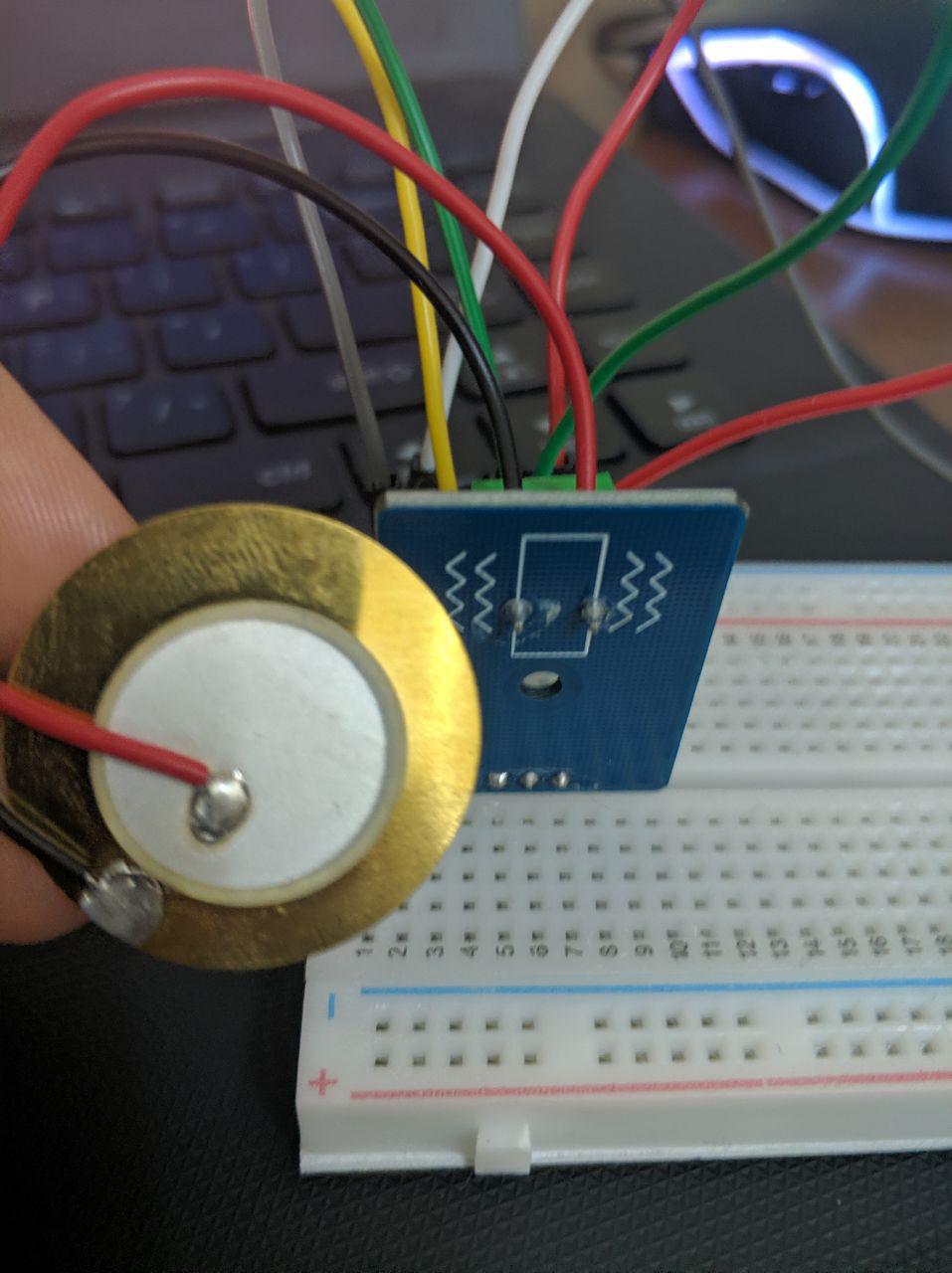
What appears to be a piezo buzzer has 3 connections to it. I'd have expected two.
6v6gt:
If you have a plain relay, you cannot drive it directly from an Arduino pin. You'll need a transistor, base resistor and flyback diode. Either that, or get a relay module with all that and maybe more.
What appears to be a piezo buzzer has 3 connections to it. I'd have expected two.
Im using this
Suppose to be two connection but i'm using this board.
ChrisTenone:
Congratulations on posting a picture we can see!
Your diagram is difficult to read it follows no conventions, uses undefined abbreviations and gives no clue as to the software used.
Please elaborate: What step-up module, what are the other components (please provide data sheets or a link to the item), and some code that illustrates how you use the signals would be good.
Thanks.
Thanks for reply. Updated post with proper elaboration