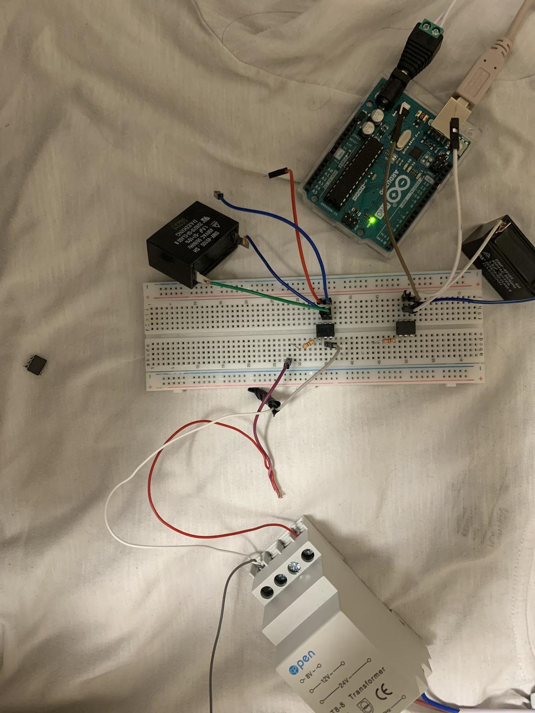
if you mean the 24V AC smart-relay. It is probably not well suited.
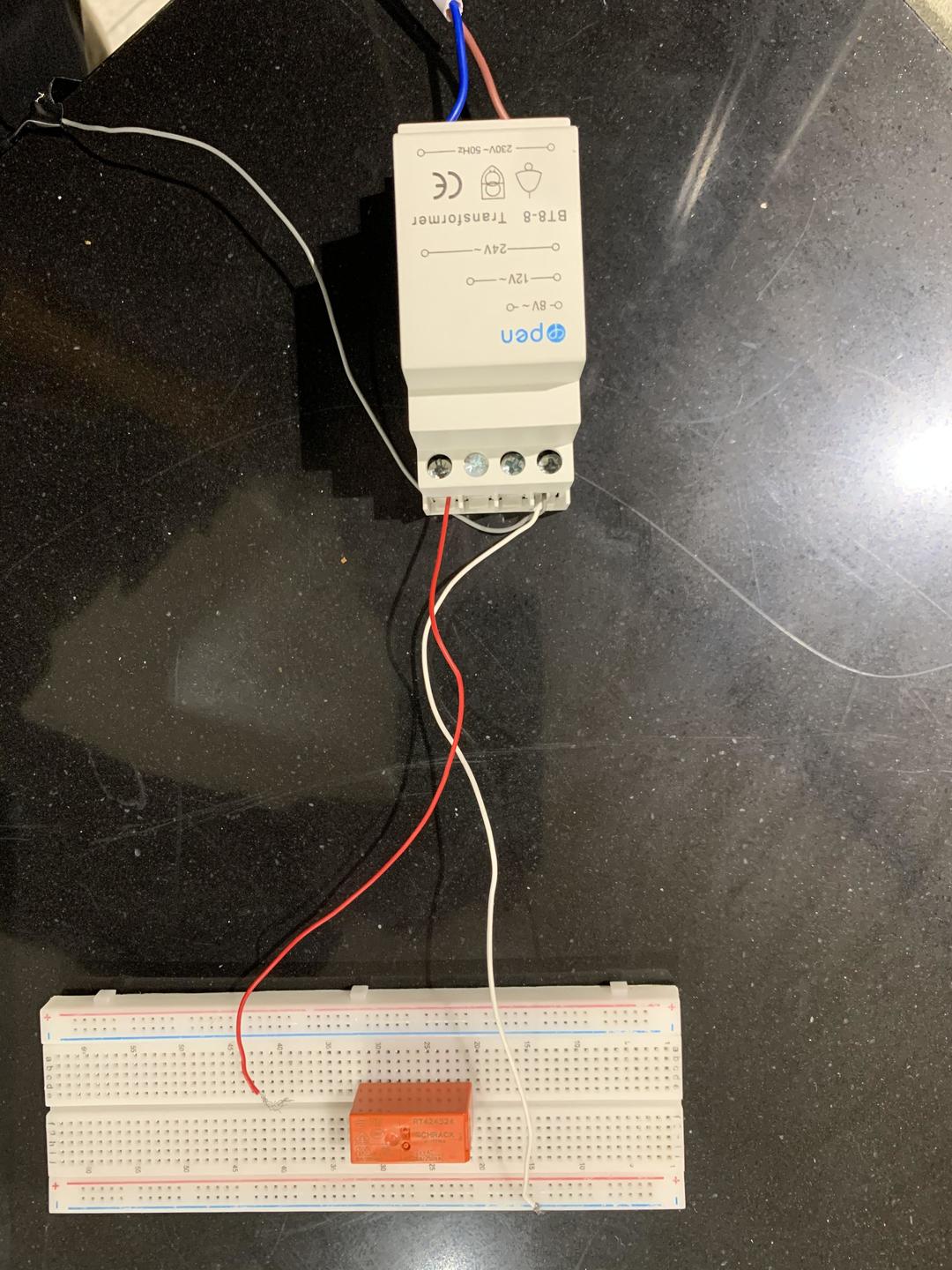
your smart-relay switches on/off 24V AC.
A relay has a coil and one or multiple switching contacts.
The coil can be seen as the input-side. The contacts can be seen as the output-side.
If the coil is connected to a "power-supply" with an apropriate voltage the coil creates a magnetfield which makes the contact switch from switched off = no power into coil
to
switched ON = power into the coil
In most cases you want to use the 5V of an IO-pin to switch a higher load. This means the IO-pin is connected to the inputside. This means The inputside has to react on 5V DC And the Outputside (the contact is connected to a higher voltage.
In your case it is the opposite. Your smart-realy "delivers 24V AC and the Smart-relay 24V must be connected to the inputside of the relay. So the inputside must be suited for 24 AC.
The link you have posted show a relay module with 5V DC-input which has an additional transistor on the inputside because the current of the relay is too big to drive the relay diectly.
So connecting 24V AC to the inputside of the linked relay-modul just creates the "magic" smoke and the modul will be destroid.
As you can see from this explanation: trying to do things real quick turn out to slow down things a lot.
The microcontroller-wolrd is NOT superstandardized like USB-devices. You have to take care of a lot more things than just does the plug fit into the socket?
the additional things are:
- do both sides have the same voltage type AC or DC?
- do both sides that shall be connected have the same voltage-range?
-can the outputside deal with the amperage of the inputside?
- in case of inductive loads do I need to add antiparallel diodes to supress voltage-spikes?
- in case of data-communication do both sides have the same kind of bus? (I2C, SPI or serial)
So to use the linked relay-module with 24V AV you additionaly need some parts to make it work:
a bridge-rectifier to convert the 24V AC to 24*1,41 = 34V DC
an additional resistor. The value of this resistor depends on the current measured at "normal" supplying the input with 5V and must be measured before the value of the additional resistor can be calculated.
So pretty much things to to.
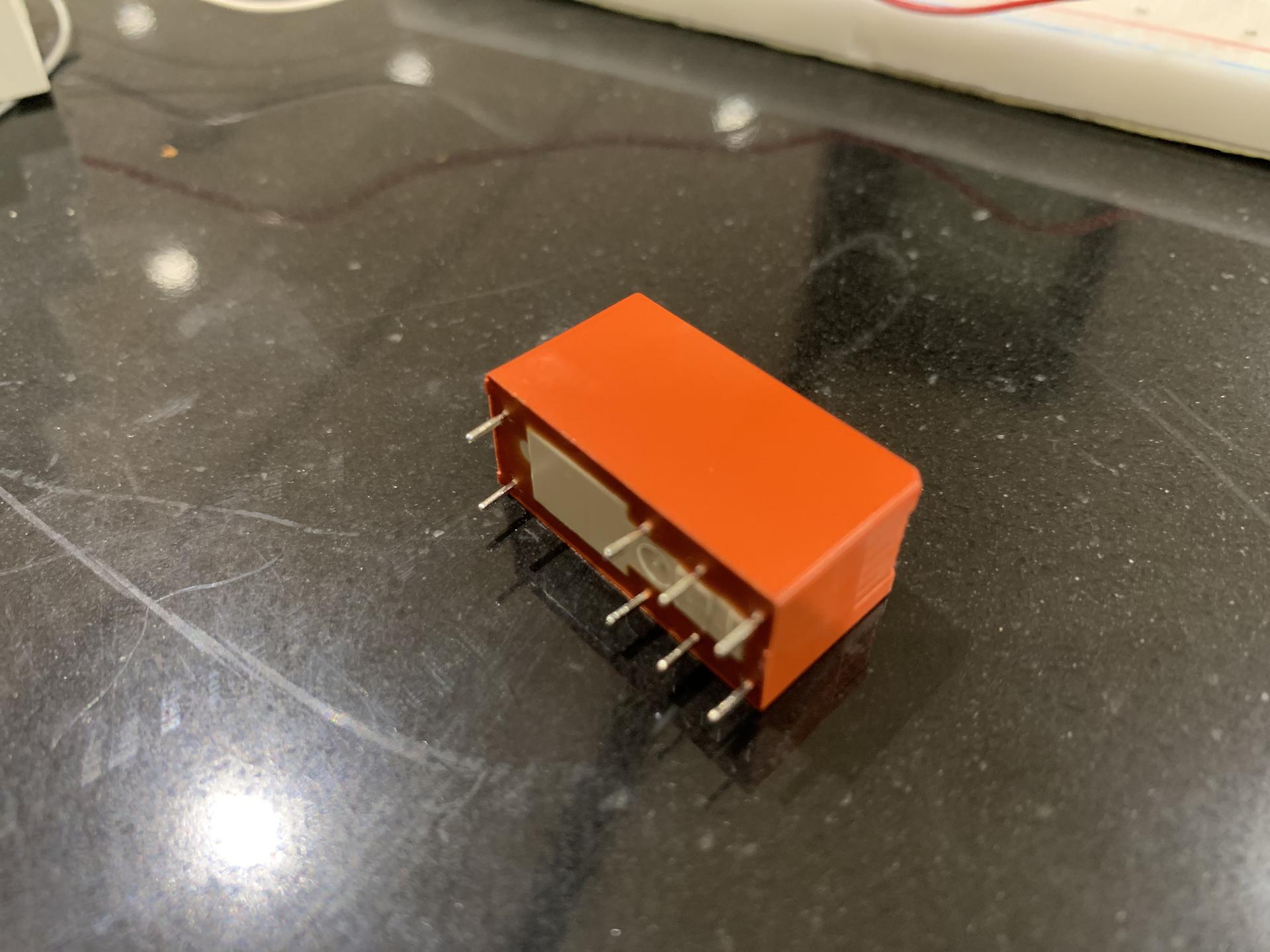
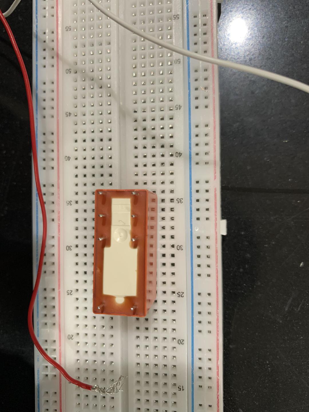
So it might be much easier to just use a relay where the coilside is specified for driving the coil with 24V AC
This is one example from a german electronic-parts-shop.
look at the specs: coil 24V AC
best regards Stefan