If the maximum is 31% more than the typical, then using the maximum will throw off calculations based on that value by a factor of 1.31.
How does using the max throw off my calculations?
What if my calculations require the use of max Rds(on)
Isn't it a valid value for Rds(on)?
@DaveX
I say that you should always use the max Rds(on) stated in the data sheet.
You say there are cases where you should use the typical instead.
Give me an example where you would use the typical value and not the max and why
Thought it might be interesting to test. ![]()
Edit
Some code to look at.
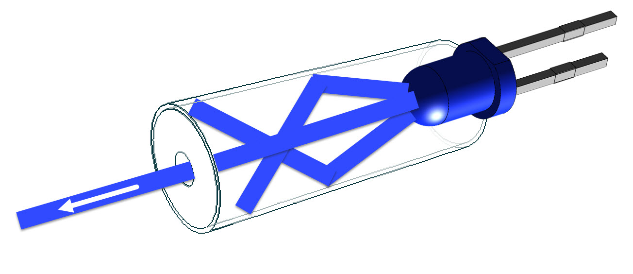
Uses an IR TX LED and IR RXVR.
This beam break sketch should give you some ideas for your project code.
//
//
//
//  Version    YY/MM/DD    Comments
//  =======    ========    ====================================================================
//  1.00       23/02/02    Running code
//
//
//

#define PULSE62_13             cli(); PINB = bit(PINB5); PINB = bit(PINB5); sei()

#define LEDon                  HIGH
#define LEDoff                 LOW

#define noRX                   HIGH
#define goodRX                 LOW

#define ENABLED                true
#define DISABLED               false

const byte heartbeatLED      = 13;

const byte IR_Receiver       = 4;
const byte IR_LED            = 3;

bool IR_LEDstate             = LEDoff;
bool rxFlag                  = ENABLED;

byte lastStatus;

//timing stuff
unsigned long heartbeatTime;
unsigned long IR_ledTime;
unsigned long startMillis;


//                                       s e t u p ( )
//********************************************^************************************************
void setup()
{
  Serial.begin(115200);

  pinMode(heartbeatLED, OUTPUT);

  pinMode(IR_LED, OUTPUT);

  pinMode(IR_Receiver, INPUT_PULLUP);

} //END of   setup()


//                                        l o o p ( )
//********************************************^************************************************
void loop()
{
  //**********************************************                h e a r t b e a t   T I M E R
  //is it time to toggle the heartbeatLED ?
  if (millis() - heartbeatTime > 500ul)
  {
    //restart this TIMER
    heartbeatTime = millis();

    //toggle LED
    digitalWrite(heartbeatLED, digitalRead(heartbeatLED) == HIGH ? LOW : HIGH);
  }

  //**********************************************                I R   L E D   T I M E R
  //is it time to toggle the IR TX LED ?
  if (millis() - IR_ledTime >= 5)
  {
    //restart this TIMER
    IR_ledTime = millis();

    //is the IR TX LED ON ?
    if (IR_LEDstate == LEDon)
    {
      //stop modulation
      noTone(IR_LED);

      //update the LED status
      IR_LEDstate = LEDoff;
    }

    //******************************
    else
    {
      //start IR TX LED modulation
      tone(IR_LED, 38000);

      //update the LED status
      IR_LEDstate = LEDon;
    }
  }

  //**********************************************                I R r e c i e v e    T I M E R
  //this TIMER should never expire if the IR beam is not blocked
  //if this TIMER is enabled, has the TIMER expired ?
  if (rxFlag == ENABLED && millis() - startMillis >= 20)
  {
    //disable this TIMER
    rxFlag = DISABLED;

    Serial.println("IR beam was broken");
  }

  //**********************************************
  //check the IR receiver
  sampleIRreceiver();


  //**********************************************
  //Other non blocking code
  //**********************************************

} //END of   loop()


//                            s a m p l e I R r e c e i v e r ( )
//********************************************^************************************************
//check the receiver
void sampleIRreceiver()
{
  byte currentStatus;

  //**********************************************
  //read the IR receiver sensor
  currentStatus = digitalRead(IR_Receiver);

  //*****************************
  //did the status change ?
  if (lastStatus != currentStatus)
  {
    //update to the new state
    lastStatus = currentStatus;

    //*****************************
    //When the TX IR LED is at 38kHz, the receiver output is LOW.
    //At this point, we should be receiving a signal from the TX IR LED.
    //
    //has the IR beam been detected ?
    if (currentStatus == goodRX)
    {
      //allow the TIMER to run
      rxFlag = ENABLED;

      //restart this TIMER
      startMillis = millis();
    }
  }

} //end of   sampleIRreceiver()


//********************************************^************************************************
For the heat example, I think you would would need use the typical/measured/actual values from the chart if you were operating below Vgs=4V. For extra safety, one could add on a x1.31 factor to calibrate for the chart-versus-max factor you calculated.
Typical/measured/actual, what are these?
I would think you would want to use the max value. That would give the the max power dissipation. Isn't that what you want when doing the heat example?
First you say use the max value for heat management, now you say the typical
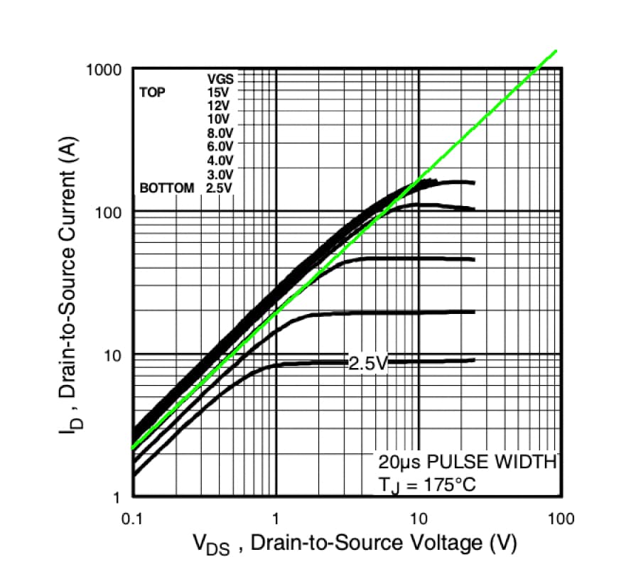
They get the curves on the chart by measuring typical/actual parts. The lower Vgs curves have larger Rds_on than the 0.035ohm max on the datasheet.
For example, they measured a (typical) Rds at Vgs=2.5V at 2A is V_ds/I_d = 0.2/3 = 0.066 ohm to 0.2/2.7=0.07 ohm, nearly twice the datasheet's max. Or way up the V_(gs2.5V,185°C) curve at 20V and 9A: Rd=2.2ohms. Using the datasheet's advertised Rds max value versus the charted typical/measured/actual values would catastrophically underestimate the Rds and heat production.
So what is the meaning of maximim?
Are you saying a typical value can be greater than the max? That makes no sense.
Typical values should be bounded by the maximum and minimum values, otherwise they are not typical but outliers.
No optical expert here either, but I read that a normal glass lense made for visible light could absorb most of the IR. That was my concern. And how do you focus this lens if you can't see the light...
In my experiments with beam break sensors a narrow beam IR LED gave me plenty of distance without optics, so why not try if it gives you the distance needed. And yes, the tube is there to absorb stray light.
Leo..
1 Like
I'm using a plastic lens so it think it should be ok. I've used a white LED to get the focal distance and then made a 3d printed mount to hold the lens and LED at the right distance. So should just be able to swap them over.
I can see the IR with a phone camera too.
I'm saying that the maximum advertised value at one operating point may be significantly smaller than the measured value at a different operating point. In these MOSFETs, as shown by the curves, Rds increases as you lower Vgs. It also goes non-linear as you increase the current.
If you are saying that Rds is < 0.035 ohm for the IRLZ44 in all situations, I must be completely misunderstanding those charts, and also that all anyone ever needs is this 0.035ohm, 45° green line. That makes things much easier. Thanks.
I never said that.
The green line represents the ohmic region. When you use the MOSFET as a switch you want to be in the saturation region. Your argument makes no sense.
Actually (in the graph), for a MOSFET as a switch, we want to operate in the Ohmic Region and Cutoff areas; where Vds ÷ Id = Rds(ON) and where Vds is very small.
We operate in the Saturation Region (constant current region) when we want an amplifier.
You are correct
You can then do the focusing experiments without pushing the IRED to the outer limits, yes?
Got some pictures of that?
Leo..
Not much to it really. It's made to slide over a 32mm PVC pipe. LED is held in place with a LED holder, and the lens just clips onto the front atm. Will need a lower half at some point so it can be glued in place.

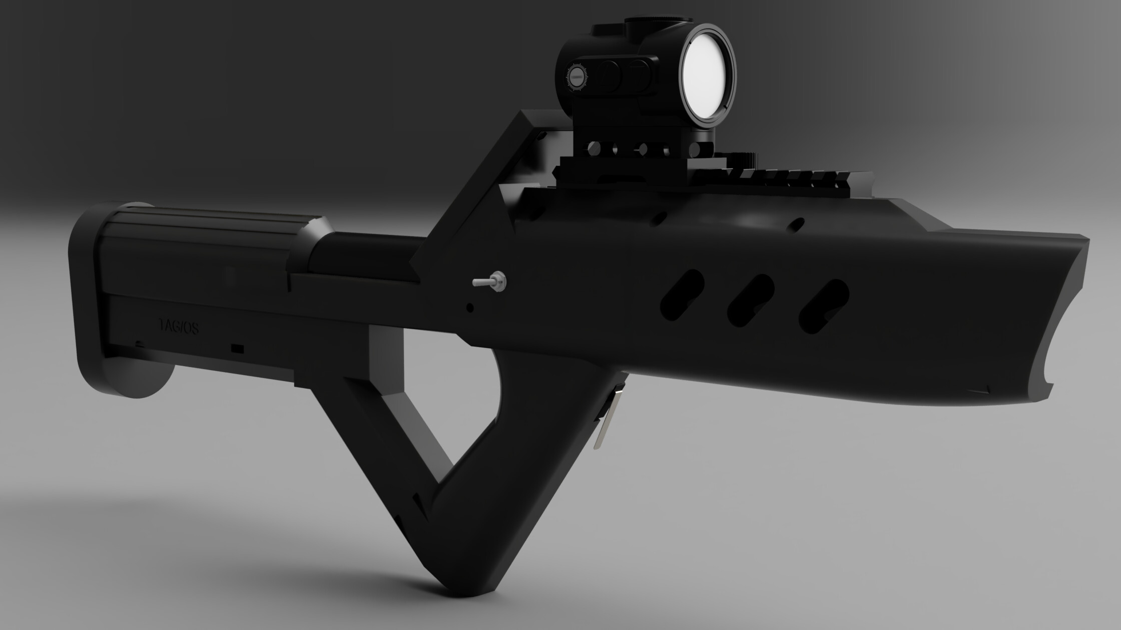
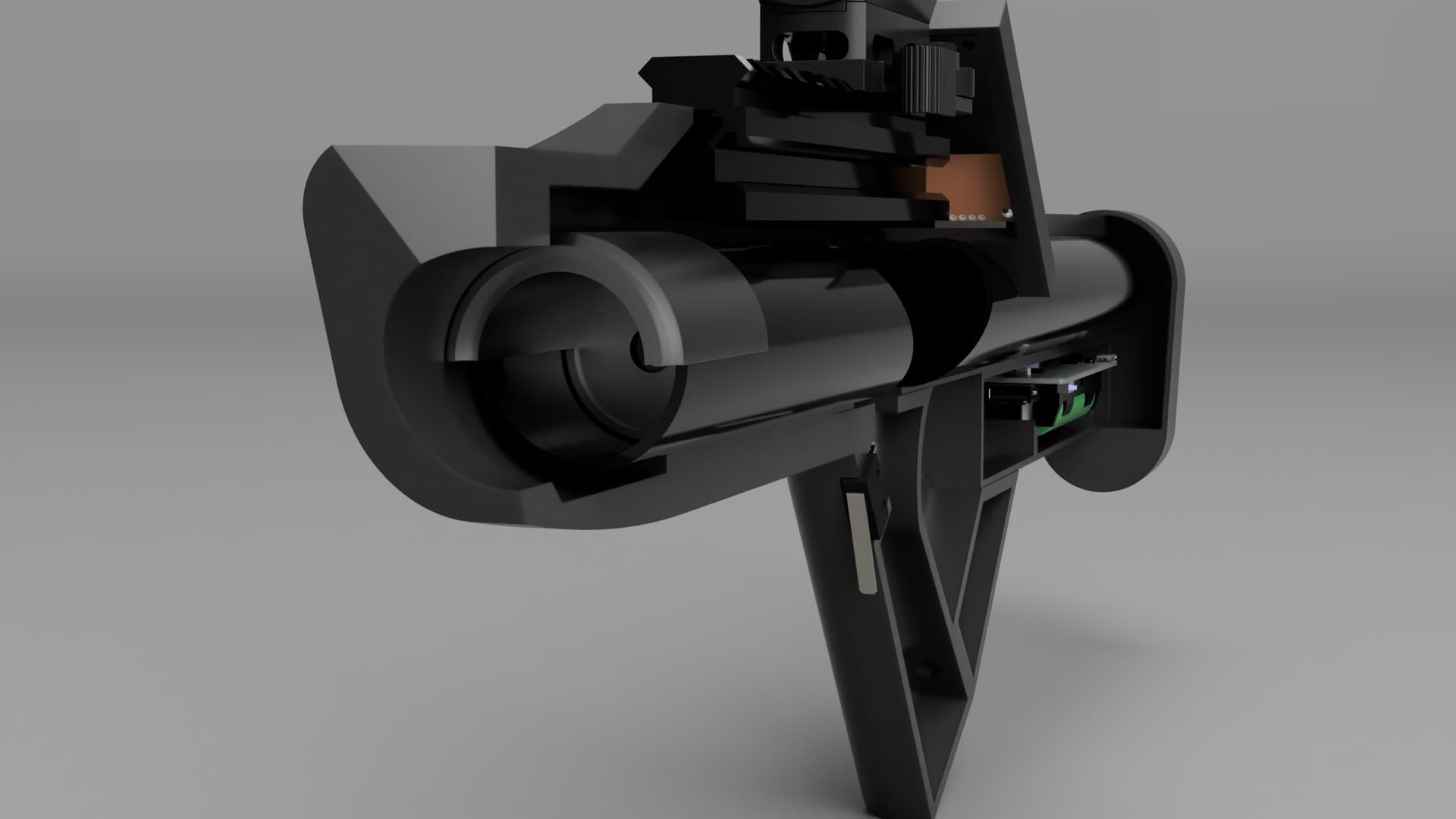
This is a render of the full design as it stands... It will have a 2.2inch TFT screen for viewing ammo count, health etc. Plus a rail on top to mount scopes/sights etc.
This topic was automatically closed 180 days after the last reply. New replies are no longer allowed.