Hi all,
I'm designing a laser tag system, with 3D printed gun, based on an ESP32 controller. I'm looking into the IR LED and how to get the best range. (i'm also using a lens to focus the beam)
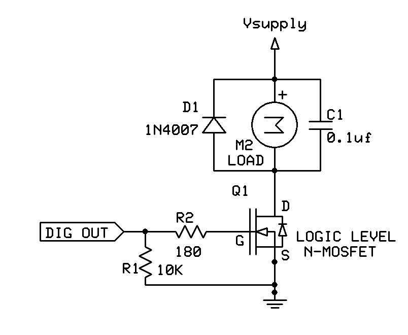
Looking at this product from Adafruit, that can apparently pulse to 1 Amp. It also suggests pairing it with this transistor.
I can supply one amp from my power supply, but i'm unsure about what resistors to use between the supply and the LED, and the ESP32 pin and the Drain pin on the MOSFET.
My understanding is that, for the LED I would need a ( 5v - 1.6v ) / 1a = 3.4 ohm resistor?
For between the ESP32 and the Drain pin, I assume it doesn't really matter what the resistor is, so pick a high one? (around 1kOhm?)
Is anyone able to validate that i'm not an idiot and this is what's needed?
I assume it doesn't really matter what the resistor is
Not correct. For the MOSFET gate series resistor, pick a low value resistor that limits the pin output current to a safe value for the ESP32. 220 Ohms may be suitable.
The "wrong way" that you posted forms a voltage divider which reduces the gate drive voltage. It is not a large effect, but the mistake is just plain stupid.
Why not simply use a narrow beam IR LED.
50m (150 feet) is not a big problem with a 7 degree narrow beam LED and 100mA LED current.
Don't use a single transistor and resistor to limit LED current. If you're driving the LED close to it's max, then a two-transistor constant current driver is much better and safer.
Leo..
I don't know how laser tag works, but that LED is rated at 100mA continuous current, with a burst limit of 1A. Will you be triggering the LED with a low duty cycle pulse, like a TV remote does, or is it continuous?
7° at 50m would be ~6m - so it could shoot 2 people stood 5 meters apart at the same time. The lens will focus the beam and make it much more accurate.
You've lost me with your diagram though!
when you say "constant current" do you mean powering it continuously at 1amp? I will be modulating the LED, sending "packets" of information - so is this still needed?
This diagram was commonly used in TV remote controls.
It's a current limiter. Max LED current is set with the value of the 6R8 resistor.
The Arduino provides the 38kHz burst, that drives the 2N2222.
Current flows through the LED/2N2222/6R8, and builds up a voltage across the 6R8.
That voltage is used by the 2N3904 to slam on the brakes if LED current gets over a set value.
Reducing the 6R8 to 3R3 will double the LED current to 200mA (still safe for a burst).
0R68 would be 1Amp, but do stock plenty of spare LEDs if you go that way.
More than 500mA also gets too much for a 2N2222/BC337.
Leo..