I did try using an OPAMP but noticed that the entire signal is being shifted to a higher voltage and not only the positive part of the signal. I only want the "ON" part of the PWM signal to be increased from 5v to 9-14v. Is that possible with an OPAMP? If it is can you please tell how to use it to get the desired result?
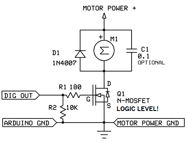
Use this circuit for a motor. "M" can be anything you are controlling with PWM, or replace M with a resistor and take the voltage output from the drain "D" terminal.
I think that removes the ambiguity of the use of the word “amplify” in post #1 and what you posted in post #8 is what the OP needs, but I guess we have to wait for the OP to confirm my interpretation.
You would need a 9-12v power supply, which is connected to the drain (or source) of the mosfet.
Gate of the mosfet should be connected to the GPIO where your PWM is generated.
GPIO must be pulled up or down depending on a mosfet you use (P or N)
Since your signal is digital . not analog, you can use hardcore class D amplifier, e.g. MOSFET transistor. If your PWM frequency is high, choose transistor with lower capacitance
PS: what you are asking for is not “amplifying“. It is a “level shifting”. Amplifying assumes that noise would be amplified too, which is probably not what you want
I was able to get this signal using the following arduino code:
int PWM_Pin=3;
void setup() {
  pinMode(PWM_Pin,OUTPUT);  /*declare D3 pin as an output pin */
}
void loop()
{
  analogWrite(PWM_Pin,31);//Duty cycle:12% frequency:490Hz
  delay(125);//Duty cycle of Square wave=50%
  analogWrite(PWM_Pin,0);
  delay(125);//Duty cycle of Square wave=50%
}
Basically i was asked to generate a PWM signal having 12% duty cycle, 490Hz frequency and the voltage being in the range of 9-14v. The PWM was to be generated only in the ON part of the square wave, hence the wave in the screenshot. But since arduino pins have a voltage of 5V. I wanted to know if there is a way to increase the voltage of the waves to the range of 9-14v. Hope i have explained it clearly