So I’m using the version 2.0 of that library because I was having issue with 3.0. It seem to be working fine with the 16 channel multiplexer but what if I want to use a 8 channel like the 74ch4051 ? Because it seem to skip the reading on channel 1 and goes straight from channel 0 to 2 ? Any hint ??
What library?
"It" being your code and/or hardware? Post the code and a schematic so we know what you are doing and how you are doing it.
Analog-Digital_Multiplexer library and the code is the one from the example available in the library AnalogSignalReadExample.ino

/**
 * This example demonstrates how to read analog signals.
 *
 * It assumes there are potentiometers connected to the 16 channels of the
 * 74HC4067 mux.
 *
 * ------------------------------------------------------------
 * Project: arduino-ad-mux-lib
 * Source: https://github.com/stechio/arduino-ad-mux-lib.git
 *
 * Filename: AnalogSignalReadExample.ino
 * Version: 1.0
 * Author: Nick Lamprianidis (adaptation by Stefano Chizzolini)
 */

#include "Type4067Mux.h"

/*
 * Creates a Type4067Mux instance.
 *
 * 1st-3rd arguments initialize SIG pin (analog input on Arduino PIN A0).
 * 4th-7th arguments are the Arduino PINs to which the S0-S3 pins connect.
 */
Type4067Mux mux(A0, INPUT, ANALOG, 8, 9, 10, 11);

void setup() {
  // Initializes serial port.
  Serial.begin(9600);
  // Waits for serial port to connect (needed for Leonardo only).
  while (!Serial)
    ;
}

/*
 * Reads the 16 channels and reports on the serial monitor the corresponding
 * value read by the A/D converter.
 */
void loop() {
  int data;
  for (byte i = 0; i < 16; ++i) {
    // Reads from channel i (returns a value from 0 to 1023).
    data = mux.read(i);

    Serial.print("Potentiometer at channel ");
    Serial.print(i);
    Serial.print(" is at ");
    Serial.print((double) (data) * 100 / 1023);
    Serial.println("%%");
  }
  Serial.println();

  delay(1500);
}
Schematic next.
It seems like you could just leave out the high order address line, turn the loop down to 8 and proceed.
Are you confident you have the low order 3 address bits, and the few other signal lines correctly wired?
Skipping 0 to 2 sounds awfully like you've got the address lines bungled, which is why we all want to see a schematic, a hand drawn that you take a picture of and post wou,d be easiest and entirely satisfying. Just be sure to clearly show all the parts and all the connections betwixt them.
a7

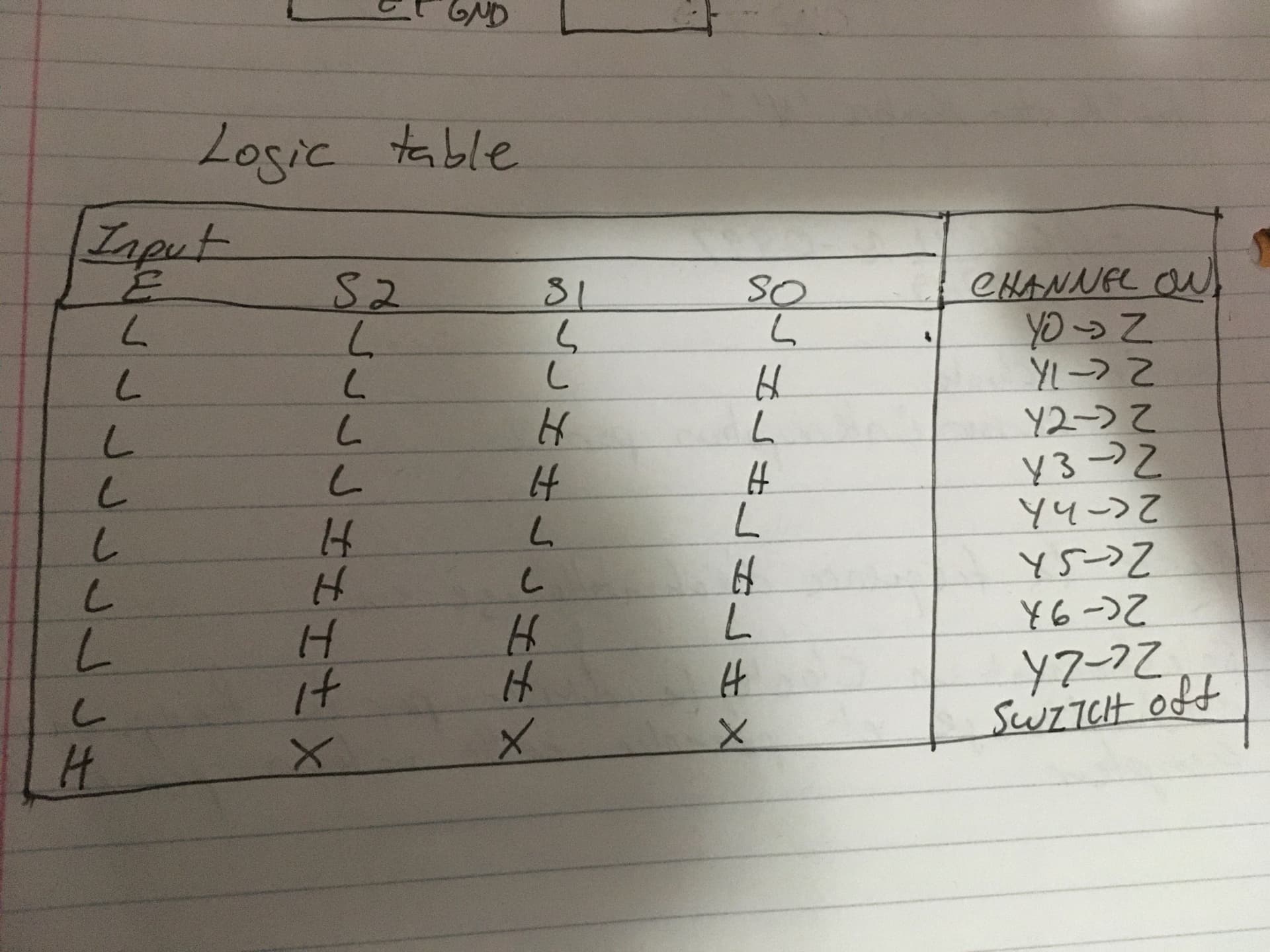
I build this function to interface with the 74hc4051 since i didnt get any luck with the library, but now, every output is connected except channel Y1. Lets say i send the logical values to s0,s1 and s2 to read channel Y0(That would be LOW,LOW, LOW) i would get the same result on all channel except channel Y1 when i should only get a logical HIGH on Y0 and nothing on the other channel.
void CH_Select(int channel, int s0, int s1,int s2){


if((channel<0)||(channel>7)){
  channel=0;
  }

  switch(channel){

    case 0:
    digitalWrite(s2,LOW);
    digitalWrite(s1,LOW);
    digitalWrite(s0,LOW);

    case 1:
    digitalWrite(s2,LOW);
    digitalWrite(s1,LOW);
    digitalWrite(s0,HIGH);

    case 2:
    digitalWrite(s2,LOW);
    digitalWrite(s1,HIGH);
    digitalWrite(s0,LOW);

    case 3:
    digitalWrite(s2,LOW);
    digitalWrite(s1,HIGH);
    digitalWrite(s0,HIGH);

    case 4:
    digitalWrite(s2,HIGH);
    digitalWrite(s1,LOW);
    digitalWrite(s0,LOW);

    case 5:
    digitalWrite(s2,HIGH);
    digitalWrite(s1,LOW);
    digitalWrite(s0,HIGH);

    case 6:
    digitalWrite(s2,HIGH);
    digitalWrite(s1,HIGH);
    digitalWrite(s0,LOW);

    case 7:
    digitalWrite(s2,HIGH);
    digitalWrite(s1,HIGH);
    digitalWrite(s0,HIGH);
    }
}
...and this is the main code
int Z_pin= 34;
int s0=35;
int s1=32;
int s2=33;
int value=0;
void setup() {
  // put your setup code here, to run once:
Serial.begin(9600);
pinMode(s0,OUTPUT);
pinMode(s1, OUTPUT);
pinMode(s2,OUTPUT);
pinMode(Z_pin,INPUT);
}

void loop() {
  // put your main code here, to run repeatedly:
//CH_Select(1,s0, s1, s2);
digitalWrite(s2,HIGH);
digitalWrite(s1,HIGH);
digitalWrite(s0,HIGH);
value=digitalRead(Z_pin);
Serial.println(value);
delay(500);
}
It all looks plausible, code and schematic. I'm not usually the one that spots a show stopping dumb error, so there is still a chance for that.
We can talk about other ways to do the address lines bit twiddling later. What you have looks correct if a bit obtuse.
I suggest experiments.
Lastly First, remove all use of anything but push buttons or other pedestrian means of supplying a logic level to the inputs of the mux. TBC I mean do not use any exotic touch sensors or such. Only when the function is working correctly 100 percent shoukd you attempt to use anything else.
Change the pinMode() on the input to INPUT_PULLUP, or better use a real 10K resistor placed in the roll of a pull-up, that is wired between the input and Vcc. Try both, two experiments.
Use whatever means you have to be sure the i/o pins you are using are valid and appropriate for the purpose they serve.
Use print stetments or better yet a logic probe to comfort confirm the states of all signals betwixt the mux and the microprocessor.
a7
The touch sensor is connected to Y0. What is connected to channels Y1-7? Nothing? If so, these inputs are "floating"which means nothing pulls them to 3.3V or ground. When your code reads them, they could read either high or row randomly. As @alto777 suggests, use INPUT_PULLUP or add an external pull-up or pull-down resistor to the Z output pin.
It’s working now. Pin 35 wasn’t sending the logical value, it kept sending 0. I just switched pin and it worked