Can't get CD74HC4067 Multiplexer to work

Hello,
I have an Arduino Uno R3 and a Sparkfun 16-channel multiplexer (CD74HC4067). I have a lot of potentiometers that I want to read values from at once, and the Uno and even the Arduino Mega don't have enough analog inputs. The multiplexer seems like it should be pretty simple to operate, just give it Vcc, ground, and a 4-bit channel selection to choose which of the 16 channels you want to access through the signal pin.

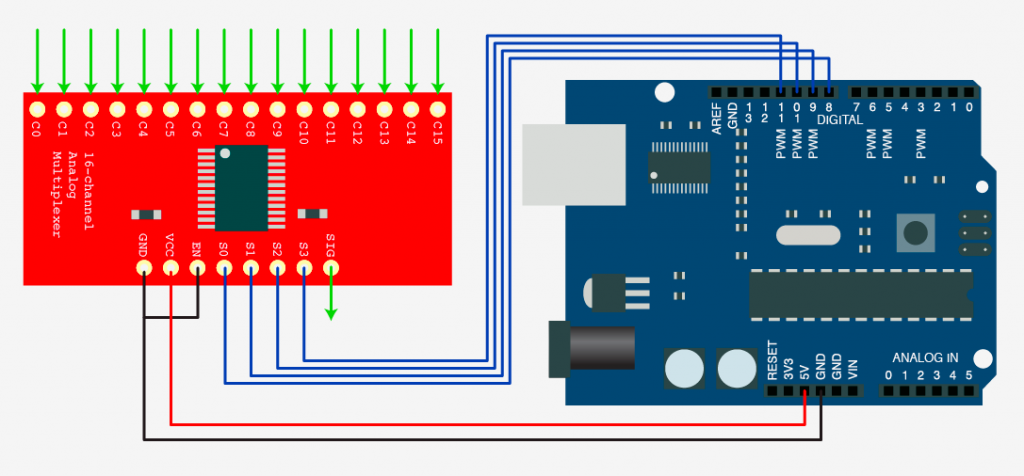
The problem is that when I hook everything up and try to access a channel, I can only seem to get gibberish out of the signal pin, even when I'm only trying to access one channel (in this case called elbow). I have mine hooked up just like this diagram from a tutorial I found (with the signal pin connected to A0, and the channel selection connected to pins 2-5):

And here is the code that I'm using:

void setup(){

  Serial.begin(9600);

  pinMode(A0, INPUT);
  pinMode(2, OUTPUT);
  pinMode(3, OUTPUT);
  pinMode(4, OUTPUT);
  pinMode(5, OUTPUT);
  pinMode(6, OUTPUT);

}

void loop(){

  digitalWrite(2, HIGH); // pins 2-5 used to select channel "0011"
  digitalWrite(3, HIGH);
  digitalWrite(4, LOW);
  digitalWrite(5, LOW);
  digitalWrite(6, LOW); // ties the enable pin low (active low)
  
  int elbow = analogRead(A0);
  Serial.print("elbow:");
  Serial.println(elbow);

I've also attempted to use the stechio Arduino multiplexer library, which simplifies the coding, but that doesn't seem to work either.

One thing that I tried was to just send the multiplexer the channel selection (0011) with NO potentiometers or other analog sources hooked up anywhere. Then I used a multimeter continuity test to see if Channel 3 and Signal were electrically connected, but they weren't, instead I would get a weird fluctuating resistance between the two.

I have a second multiplexer which seems to be exhibiting the same issue. Is there anything I'm missing here?

You can't use the VOM, how do you know the signal is 'gibberish' it is analogue right?

You have provided contradictory information.

You say you have the multiplexer hooked up "just like this diagram from a tutorial I found".

Except that you don't have the selection pins hooked up to the same pins, you're trying to control the /EN input even though it's grounded in the picture, and the picture doesn't even have the common I/O pin hooked up to anything.

So, if you do indeed have the multiplexer hooked up "just like this diagram from a tutorial I found", I'm not at all surprised that you're getting nonsense.

Show us your connections. Not some "it's just like this except it's totally different" picture you plucked off the internet.

Oh, and you've made no mention of grounding all unused inputs on the multiplexer. You are grounding all of them, right? You're not leaving CMOS inputs floating and expecting things to work properly, right?

2 Likes

Try this sample sketch. I modified it a bit but you should be able to understand. This is for just ONE analogue pin so you get used to what you see.

/*
  Analog input, analog output, serial output

  Reads an analog input pin, maps the result to a range from 0 to 255 and uses
  the result to set the pulse width modulation (PWM) of an output pin.
  Also prints the results to the Serial Monitor.

  The circuit:
  - potentiometer connected to analog pin 0.
    Center pin of the potentiometer goes to the analog pin.
    side pins of the potentiometer go to +5V and ground
  - LED connected from digital pin 9 to ground through 220 ohm resistor

  created 29 Dec. 2008
  modified 9 Apr 2012
  by Tom Igoe

  This example code is in the public domain.

  https://www.arduino.cc/en/Tutorial/BuiltInExamples/AnalogInOutSerial
*/

// These constants won't change. They're used to give names to the pins used:
const int analogInPin = A0;  // Analog input pin that the potentiometer is attached to
const int analogOutPin = 9;  // Analog output pin that the LED is attached to

int sensorValue = 0;  // value read from the pot
int outputValue = 0;  // value output to the PWM (analog out)

void setup() {
  // initialize serial communications at 9600 bps:
  Serial.begin(9600);
}

void loop() {
  // read the analog in value:
  sensorValue = analogRead(analogInPin);
  // map it to the range of the analog out:
  outputValue = map(sensorValue, 0, 1023, 0, 255);
  // change the analog out value:
  //analogWrite(analogOutPin, outputValue);

  // print the results to the Serial Monitor:
  Serial.print("sensor = ");
  Serial.print(sensorValue);
  Serial.print("\t output = ");
  Serial.println(outputValue);

  // wait 2 milliseconds before the next loop for the analog-to-digital
  // converter to settle after the last reading:
  delay(2);
}

I apologize that my post was very unclear. As I had said, I hooked up the selection pins to channels 2-5. I understand I should have been clearer that the picture that I provided has those pins connected to 8-11, whereas mine are different. I declared 2-5 as the outputs in my code, and hooked it up as such.

As for the enable pin, I wrote in my code to set it LOW, which I had assumed (perhaps wrongly) would be the equivalent of grounding it, however I will point out something that I should have mentioned in my original message which is that I did try the configuration of the enable pin as depicted exactly in the illustration, where I connect it directly to ground, but I had the same result.

For the I/O pin, as I also said, I hooked it up to A0, but again, I could have made that a lot clearer. I was unintentionally very ambiguous when I said that mine was hooked up "just like" the picture.

However, I think you may have illuminated what could be the source of my problem. I did in fact leave the other channel pins unconnected. I actually did not know that leaving the CMOS pins like that would cause an issue. I had assumed that electrical continuity between the channel pins and the signal pin was simply facilitated and switched by the Mux, kind of like transistor opening and closing, but I see now that my basic understanding of the device was likely flawed. I will attempt to remedy that and see if it fixes the problem.

Analog mux I/O in CMOS is kind of "different". It's not like leaving a CMOS digital input pin floating, which is a definite do not do and will cause all kinds of problems. But I've never been comfortable with the idea of leaving unused analog I/O pins floating and always tie weakly them to either Vss or Vdd.

Hi,
What analog level have you got applied to the input channel on the 4067 that you are attempting to read.

What voltage?

Can you post some images of your project?
So we can see your component layout.

Thanks.. Tom.... :smiley: :+1: :coffee: :australia: