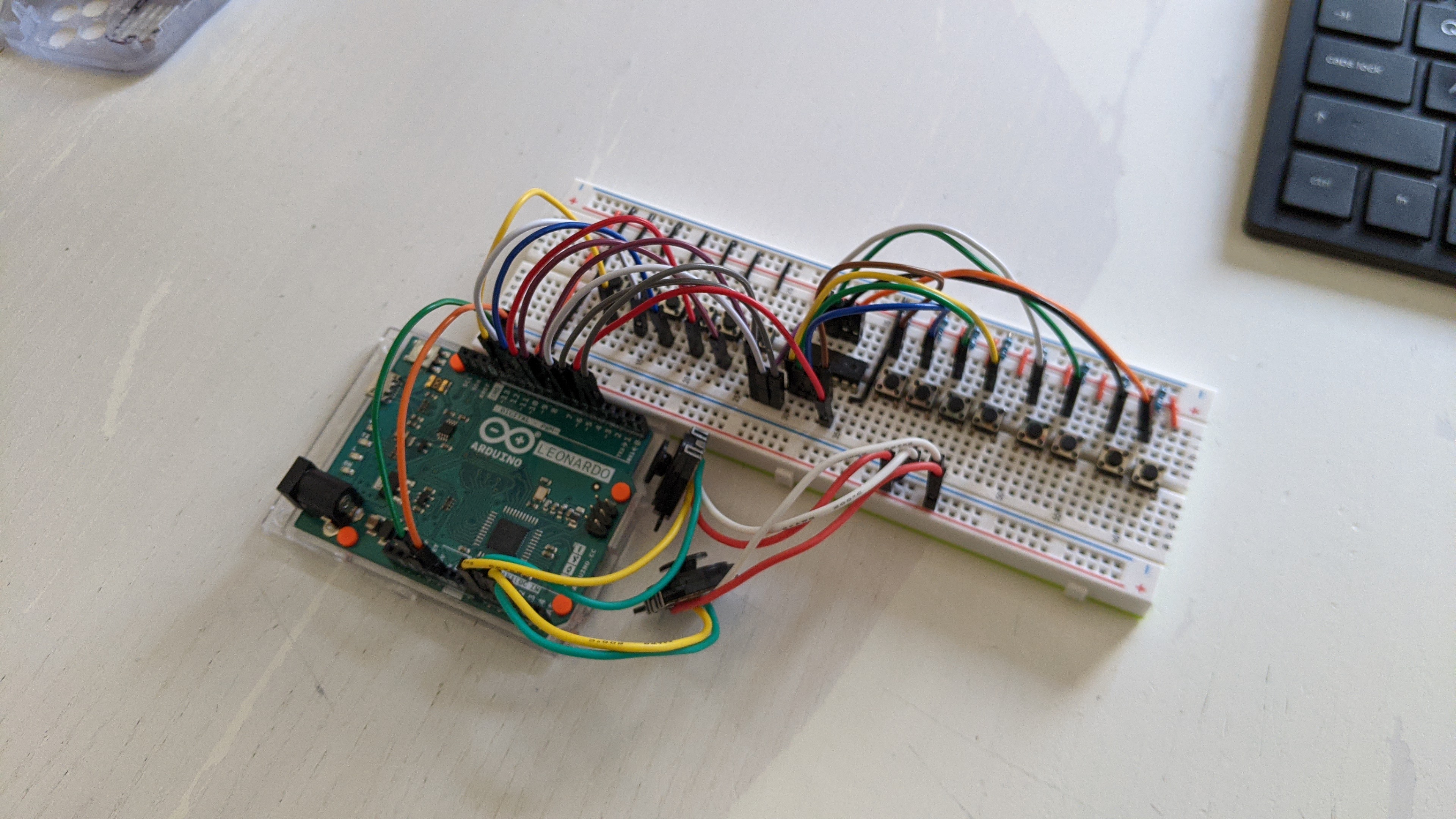
I'm trying to design my own USB gamepad controller and I have created my own prototype in a breadboard that seems to work relatively well.
I have run into an issue that has puzzled me quite a bit.
You can find the circuit diagram attached to this post but here is a summary of main components used:
Arduino Leonardo (ATmega32u4)
74HC165 shift register
2 PSP analog thumbsticks
14 push buttons
The the issue that I have identified is that whenever I press one of the buttons attached to the shift register, the readings from the analog joystics "jump" up as if they more current was going through them.
The values remain "up" for as long as any of the buttons attached to the shift register remain pressed, going back to normal as soon as I release it/them.
The circuit is meant to be powered from the USB port in the Arduino Leonardo and this issue is only evident when this is the case.
If I power the board through the DC input separately, the problem disappears. (Keep in mind that the board would still be plugged to my laptop via USB to check the readings)
I have tried placing a few capacitors here and there to decouple the parts of the circuits, but my electronics knowledge is fairly limited and I may have not done so correctly.
The arduino code is also in the attachments, though I don't believe the problem to be there...
Thank you kindly for any guidance you are able to offer me!
You have the same ground line with a GND1 and GND2!
Connect the ground from your devices connected to the analogue inputs to an unused GND pin on the Arduino not to the ground connected to the shift register.
The problem you have is called “ground lift” and is a common thing.
@Grumpy_Mike:
I tests using separate GND pins for GND1 and GND2, but this had no effect...
It would appear to me that the Arduino Leonardo board connects the both pins together internally, which ends up being the same as having GND1 and GND2 connect to the same pin.
@JohnRob:
Thanks! Very informative, though it does confuse me a bit.
While having the common ground allows the whole prototype to "work", it also appears to interfere with the analog readings.
It seems to me I need to follow the advice/guidance both of you gave me.
I need to have a common ground but I also need to find a way of isolating the analog and digital part of the circuit.
It would also be in line with the text on this post
[...] The normal approach is to keep analog and digital ground and power separate, except that the grounds are tied together at one point (not on a high-current path). The two grounds are ideally coupled with an RF-choke to reduce noise-injection at high-frequencies.
Thus I attempted to connect the digital part of the circuit to the v5 pin and the analog part to the v3.3 line, to both using different GND pins (see attachment for updated circuit diagram)
This sort approach appears to be a step in the right direction, but the ground lifts are still there.
Presumably all GND pins end up connecting to the same USB GND line... and maybe that is the problem (mere speculation)
Like before, if I power the board via the DC input, the problem disappears, or it is at least mitigated to the point that I can't perceive it.
I am going to change the code to push the values of the analog pins to the serial monitor. That way I may be able to tell if there is any interference this way, however small.
If there isn't any, I may be that the answer to my question is within the Ardunio Leonardo schematics.
Should I continue proceeding this way or am I way off?
This problem may be exacerbated if some of the ground or supply hook-wires aren't
of decent quality and making solid contact with the headers - some hookup wires you
can get are very thin internally. I make my breadboard hook-up wires myself from solid-core
0.6mm diameter copper wire, as this has good current handling and the lack of miniature
crimp connections avoids any issues of faulty crimping of thin wires (crimp connectors are
not designed for very thin wire).
It would appear to me that the Arduino Leonardo board connects the both pins together internally, which ends up being the same as having GND1 and GND2 connect to the same pin
Yes it is. But the whole point is that you are generating a star wiring system which is where the grounds are connected at one point, thus making the currents flowing in the analogue ground not interfere with the currents in the digital system.
You could also add some power supply decoupling on your analogue devices.
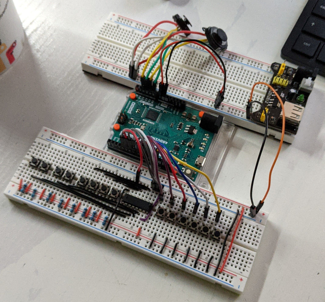
I have made a few adaptations to the circuit (see attachment):
I have introduced an breadboard power supply to the circuit (represented by a battery in the diagram) in order to help my understanding of how is the current flowing. Now the Leonardo is powered by through the Vin and no power is directly connected to the board.
It helps me to better visualize how I'm star wiring my GNDs.
I have replaced most lines with solid-core 0.6mm copper hook-up wires. A bunch remain, but the connections in the prototype feel more secure and I feel like I can rely on them.
I have updated the code (also attached) to show me the analog readings in the serial monitor in the Arduino IDE.
The problem is still there but I have made some progress.
I'm confident now that I made mistake describing my problem.
I say that the analog readings were surging UP whenever I pressed buttons attached to the shift register.
However, this was incorrect and it was evident to me after having a look at the actual readings in the serial monitor.
What is actually happening is that the values are actually going **DOWN **whenever I press buttons attached to the shift register.
I think now that looking for ground lifts in the circuit was just a red herring.
I think now that maybe what I need to add some capacitors somewhere, though I do not know where or how large they should be ... may need to read more.
Just a general troubleshooting approach, I would disconnect all the signal connections between the shift register and the arduino board. If the issue still exists then the problem exists in the power/ ground circuitry. If not then the data lines are likely involved.
Next question, how much does it jump? (in counts)
Why do you use 3.3V on your joystick? If your joystick can operate on 5V AND you are using the 5V as the A/D reference then changes in 5V absolute value will cancel out.
Also, the Vin pin of the Leonardo takes a path through the voltage regulator so is not suitable for if you are using a 3.3volt power source. Use the 5v pin instead.
@JohnRob: Thanks for the troubleshooting tip! Will keep that in mind for the future.
With the setup described by the latest batch of pictures, the drops are of 21 on average (though they are slightly different for each analog pin).
If I disconnect all the digital pins from the board, the readings are much the same.
As far as understand it, the current setup uses 3.3V for everything, thought he v2 setup did use 5V for digital and 3.3V for analog (which may have been a mistake)
Nevertheless, I connected 5V on the Vin pin and the readings continued to show that there is a 21 average drop whenever I press a button.
@6v6gt:
Thanks for flagging that using 3.3V on the Vin pin is incorrect.
However, if I connect 3.3V to the 3.3V pin, the readings differentials go from averaging 21 to approximately 50.
I did this because your suggestion of connecting 3.3V to the 5V pin "sounded" wrong to me.
However, when I did exactly what you said, the analog readings drops I was experiencing when down from 21 to averaging 1-2 for all analog pins when I press any buttons attached to the shift register.
This values are far more tolerable and I could average them out in the code (which would be the right approach anyway)
It also seems to work well for 5V and 3.3V (so long as I always connect the supply to the 5V)
Does this mean that the 5V label on the board pin is not necessarily correct for all setups?
@Grumpy_Mike: I have yet try your decoupling suggestion, but I will do for sure. Seems to me that it is the right way to go to further rectify the readings.
"You could also add some power supply decoupling on your analogue devices."
"Decoupling, use a 0.1uF ceramic ( must be ceramic ) in parallel with something large like 47uF."
I have tried to implement both sets of suggestions.
This was done to the best of my knowledge.
I hope they are compatible.
I do have a DMM but I only know how to use it to check connectivity.
I am a bit in the dark when it comes to use it as anything else... I'll get there eventually.
The attachments outline the current setup and circuit.
The signals are VERY stable now when using 5V Supply.
It becomes a bit less so (+/- 8-10 jumps) when using 3.3V (still connecting through the 5V pin of the Leonardo)
I have a few questions:
The setup places the ceramic capacitors "before" the electrolytic ones.... Is this correct?
Are any of these capacitors redundant?
Are the working voltages for the electrolytic caps meaningful? Are they just a maximum?
Why is there a difference when using 3.3V?
Would the caps values need to change if using 3.3V instead fo 5V?
The ceramic caps are labelled 104. I took this to mean 0.1uF... Is this correct
I ask about 3.3V a lot because this might become part of a larger project later and I not know if using 3.3V may end up being a constraint down the line.
At any rate... really happy with the current setup!
I'm also very grateful for all the support!
Many Thanks to all of you!
The setup places the ceramic capacitors "before" the electrolytic ones.... Is this correct?
The ceramic capacitor should be closest to the chip. The inductance of any lead will reduce the effectiveness of the capacitors. This is not so important with the large capacitance because these have a high inductance anyway. See:- http://www.thebox.myzen.co.uk/Tutorial/De-coupling.html
Are the working voltages for the electrolytic caps meaningful? Are they just a maximum?
They are a maximum so they are meaningful. As a rule don't apply more than 80% of the maximum voltage to a cap.
Why is there a difference when using 3.3V?
Are there?
Would the caps values need to change if using 3.3V instead fo 5V?
No.
The ceramic caps are labelled 104. I took this to mean 0.1uF... Is this correct
Yes the last number is the number of zeros, with the value in pico farads (10-12 Farad)