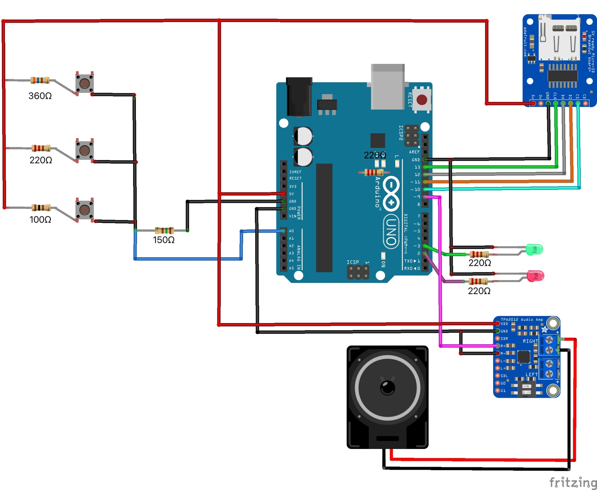
My project reads the A0 input generated by a number of buttons wired in series with stepped resistors. That part works fine as, depending on which button is pressed, I get varied inputs. The issue I'm presently trying to deal with is why the A0 reading doesn't revert back to (or close to) zero after the button is released.
I tested the functionality using this sketch:
int buttonInput = 0;


void setup(){

  pinMode(A0, INPUT);

  Serial.begin(9600);
}

void loop(){

  buttonInput=analogRead(A0);
  Serial.print("A0 reading:");
  Serial.println(buttonInput);

  delay(2000);
}
With this result:

When the button is pressed the reading jumps to 272 and then immediately drops back to 3 or 4 when it's released. This is the behaviour I expect to see.
However, when I insert the same A0 read functionality into this sketch:
#include <SD.h>                      // SD library
#define SD_ChipSelectPin 10  //pin connected to CS pin on SD card.
/* Other SD card pin connections:
 *  CS  - 10
 *  SCK - 13
 *  Miso  - 12
 *  MOSi  - 11https://support.arduino.cc/hc/en-us/sections/360003198300
 */
#include <TMRpcm.h>          //  also need to include this library...
#include <SPI.h>

TMRpcm tmrpcm;   // create an object for use in this sketch
const int greenLEDPin = 2;    // LED connected to digital pin 2
const int redLEDPin = 3;     // LED connected to digital pin 3
int buttonInput = 0; // current analog value read from pin A0
int buttonNumber = 0; // which one of the 7 selector buttons activated bnased on buttonInput value
int tuneSelection = 0; // which set of songs/tunes selected based on reading of pin A1
int tuneInput = 0; // analog read from pin A1

void setup(){
/*  Set the volume and check that the SD card is installed and operational.
 *  Set red LED flashing if not, else turn on green LED.
 *
 */
// set the analog pin as input

  pinMode (A0, INPUT);

//set the digital pins as outputs

  pinMode(greenLEDPin, OUTPUT);
  pinMode(redLEDPin, OUTPUT);
  tmrpcm.setVolume (6);
  tmrpcm.speakerPin = 9; // speaker output pin

  Serial.begin(9600);
  while (!SD.begin(SD_ChipSelectPin)) {  // see if the card is present and can be initialized:
    // If card not ready, flash red pin
    Serial.println("SD fail");
    digitalWrite(redLEDPin, HIGH);   // turn the LED on (HIGH is the voltage level)
    delay (1000);                // wait for a second
    digitalWrite(redLEDPin, LOW);    // turn the LED off by making the voltage LOW
                        // wait for a second

  }
  Serial.println("SD read OK");
  digitalWrite(redLEDPin, LOW);
  digitalWrite(greenLEDPin, HIGH);
  delay(500);
  }


void loop(){

  /*tuneSelection = analogRead (A1); // determine which selection of tunes/sounds based on pot position

 if (tuneInput >= 0 && tuneInput <= 200)
  {tuneSelection = 1;
  }
  if (tuneInput >= 201 && tuneInput <= 400)
  {tuneSelection = 2;
  }
  */
  tuneSelection = 1;
  buttonInput = analogRead(A0);  //Check if a button has been pressed

  Serial.print("A0 reading: ");
  Serial.println(buttonInput);

  if (tuneSelection = 1)
  {
    if (buttonInput >= 30 && buttonInput <= 110)
    {
      tmrpcm.play ("Raffi1.wav");
      while (tmrpcm.isPlaying ())
      {
        digitalWrite(redLEDPin, HIGH);
        digitalWrite(greenLEDPin, LOW);

        delay (5000);}
    }

    if (buttonInput >= 111 && buttonInput <= 175)
    {
      tmrpcm.play ("Raffi2.wav");
      while (tmrpcm.isPlaying ())
      {
        digitalWrite(redLEDPin, HIGH);
        digitalWrite(greenLEDPin, LOW);

        delay (5000);}
    }
  }
      digitalWrite(redLEDPin, LOW);
      digitalWrite(greenLEDPin, HIGH);

      while (buttonInput>=30)
      {
        buttonInput=analogRead(A0);
        Serial.print("A0 reading: ");
        Serial.println(buttonInput);
        delay(3000);
      }

}
I get this result:

A button press generates a reading of 352 but, when released, the A0 reading only drops to the 120 range, which creates a problem in my code.
Can anyone explain what's happening here and/or what I've done wrong?
Thanks.