Analogue Read/Write Behaving As Binary

Hi, my goal is to design a system to allow two chips to talk to each other using sinusoidal signals through an analogue pin. After working on some theory, I've now moved to the hands-on side of things.
Before I can really get started, I need to be able to verify that I can transmit a simple analogue signal from the pin of one microcontroller to the pin of a second microcontroller. I test this by sending a basic sine wave through the A0 pin of the first microcontroller (lets call it MC1) to the A0 pin of the second (lets call it MC2). My problem is that when I receive the signal, it seems to magically transform from an analogue waveform to a digital waveform.

Here is the circuit design I'm using:

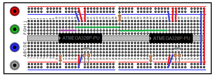
Note: The rails are being powered from the empty arduino uno board that I'm using to program the chips. Also, the blue wire at the right end of the board is supposed to be connecting the negative rails. It would appear that I made a mistake there in the diagram.

I've tried this with the resistor on row 30 going to both ground and the 5V line, using only the green wires (for communication between the chips), and using only the purple wire (sending the signal from A0 to A5 on the same chip) and I always get a binary wave at the end.

Here is the code I use on MC1 to get the values I want:

const int OUTPUT_PIN = A0;
const int INPUT_PIN = A5;
const int FREQUENCY = 1;

void setup()
{
    pinMode(OUTPUT_PIN, OUTPUT);
    pinMode(INPUT_PIN, INPUT);
    
    Serial.begin(19200);
}
void loop()
{
    //Get an accurate reading for the current time
    float seconds = float(micros())/float(1000000);
    //Defines a sin wave with the desired frequency oscilating from 0 to 1000
    int signal = sin(2*PI*FREQUENCY* seconds)*500 + 500;
    analogWrite(OUTPUT_PIN, signal);
    
    //to print the recieved values (to print the original signal, I comment out this line)
    signal = analogRead(INPUT_PIN);
    
    Serial.println(signal);
}

//I have checked to verify that the seconds variable is working as desired.

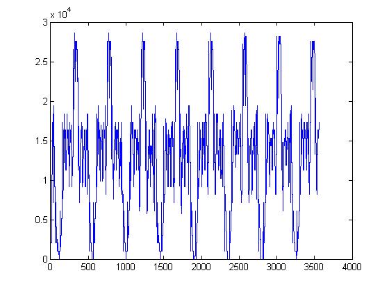
Using this, I copied some data from the serial monitor and plotted it using MATLAB to help answer some questions. These are the graphs I made:

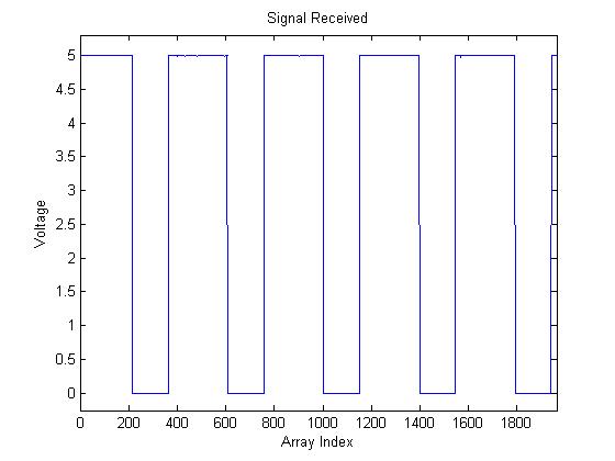
NOTE: These signals are taken from different runs and are not intended to line up

Using these graphs I was able to confirm that I was generating the desired sin wave properly, and that my suspicion that the signal received was a binary wave was correct. The zoomed in graph is there to illustrate that there are no points between high and low, so I can be fairly certain that the sine wave is not simply being chopped off at the top and bottom (I checked several transitions in this way, no intermediate values). Also, noise is minimal.

I am using two ATMEGA328P-PU microcontrollers (the chip from the arduino uno), and I am programming the chips by connecting the TX, RX, and reset pins to an arduino board without a chip on it. This method of programming and using chips has worked for me in the past, but I have never used analogue signals with these particular chips, so I will accept the possibility that these chips are defective.

Loading the fade example and preparing the circuit, the LED does not fade, it turns on and off crisply (acting like a binary switch instead of a dimmer). I tried this with two different LED, which leads me to suspect there is a fault in my use of the analogWrite function (whether it be in the hardware or the software), but if I used this incorrectly, I acknowledge that I may also have used the read function incorrectly.

Being able to transmit an analogue wave like this is imperative to my project, so I would greatly appreciate any feedback. Sorry if this isn't the right category btw, I wasn't sure where to put it.

Kaden Burgart

Why reinvent the wheel ? That's called an FSK modem.

Why reinvent the wheel ? That's called an FSK modem.

Actually, re-inventing the wheel is kind of the point of the project. I hope to use this method to transmit several signals in parallel by combining different sine waves, sending them, and then using a DFT on the other side to decode the original signals.

Only certain pins can be used for AnalogWrite. A0 is not one of them. analogWrite() - Arduino Reference

Full duplex FSK is four I think

Only certain pins can be used for AnalogWrite. A0 is not one of them. analogWrite() - Arduino Reference

Thank you very much for that, it explains a lot. However, reading that page it appears that the analogWrite function works with PWM. Doesn't that mean that reading the signal will simply result in another square wave with the frequency varying with the amplitude of the sine wave I try to send? If so, does that mean I have to use a whole bunch of pins to make a DAC or is there another way to produce the signal I'm looking for?

Dac breakout bd

I am using two ATMEGA328P-PU microcontrollers (the chip from the arduino uno), and I am programming the chips by connecting the TX, RX, and reset pins to an arduino board without a chip on it. This method of programming and using chips has worked for me in the past, but I have never used analogue signals with these particular chips, so I will accept the possibility that these chips are defective.

Nothing wrong with the chips. To be fair to beginners to arduino, they didn't do beginners any favors by naming the function analogWrite(), where it should really have been named pwmWrite(). The mega328p does not have a true digital to analog converter internally, it does however have some hardware timers that can be configured to output a signal at a constant frequency but with a variable duty cycle (the time the signal is HIGH) that can be set to anywhere from 0% to 100% HIGH over 256 range of values. To convert this digital PWM signal to a true analog voltage involves wiring it to a low pass filter (R/C network) and usually then buffering it with a unit gain op-amp. Of course another method would be to utilize an external DAC module.

Not to further confuse the issue but the analogRead() function is a true ADC function that the 328P has built into it and converts any analog voltage in the range of 0 to +5vdc into a 10 bit digital value thus converting the voltage to a digital value from 0 to 1023.

That help?

Thank you retrolefty, very helpful!

I'll be looking into ordering an external DAC then I think. I am curious though. Obviously since the amplitude is itself transmitted with a signal of varying frequency, the maximum analogue frequency that I can successfully transmit and decode will be lower. Any ideas what ball park that frequency might be in?

Also, would it be a terrible thing to program the DAC into the receiving chip? It doesn't seem like it would be overbearingly difficult to write one.

They always jump in wiithout checking to see how deep it is

Obviously since the amplitude is itself transmitted with a signal of varying frequency,

Not sure I understand your question, but again PWM in not a varying frequency, but rather a fixed switching frequency with a variable duty cycle. Much info on the net about PWM.

Lefty

Sorry, I meant a varying duty cycle not a varying frequency. I see why letting the chip use a program to act as a DAC could be problematic as well. My initial attempts at an algorithm yield a signal that looks like this:

My question is, considering that analogWrite operates using PWM, what would be the highest frequency of signal I could transmit with a DAC?

The maximum frequency of an analog sine wave generated by PWM depends on the PWM frequency, which for AnalogWrite varies from one Arduino model & pin number to another (but there are many other PWM options), the low pass filter used, and the allowable distortion. Here is a nice summary of DAC options for Atmega Arduinos Embedded newbie: Review of Arduino DAC solutions