Title says it all..
I finally got on the bandwagon and ordered up some ESP8266 modules..
(some 01's to play with.. and a couple 12's if I ever need want to embed one into a custom PCB or something)
however.. right from the gate, I cant even get an AT command to return 'OK'..
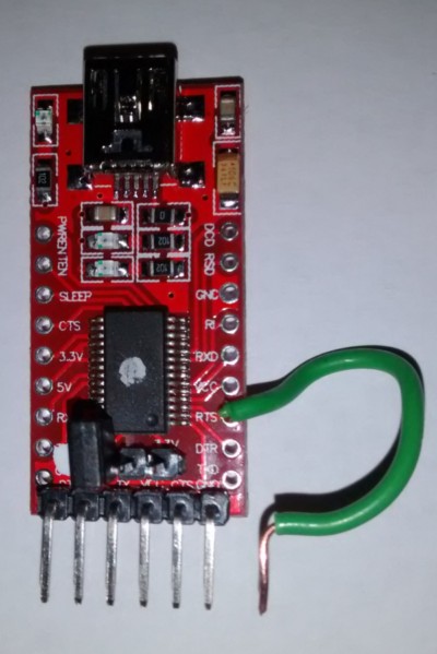
I am currently using my old, trusty CP2012 usb programmer (that I have used many times before for custom boards, pro-mini's..etc)
I have also tried adding in/using an external power source (bench top psu) to power the ESP module as I read the CP2102 might not be able to provide enough current.
attempt 1:
ESP01 PINOUT:
GND >> GND (CP2102)
VCC >> +3.3v (CP2102)
RX >> TX (CP2102)
TX >> RX (CP2102)
CH_PD >> +3.3v (CP2102)
RST >> (tried both connected to +3.3v, connected to nothing, and DTR pin on CP2102)
GP00 >> GND (CP2102)
attempt 2:
ESP01 PINOUT:
GND >> GND (external psu) >> GND (CP2102) (all three connected)
VCC >> +3.3v (+3.3v external psu)
RX >> TX (CP2102)
TX >> RX (CP2102)
CH_PD >> +3.3v (CP2102)
RST >> (tried both connected to +3.3v, connected to nothing, and DTR pin on CP2102)
GP00 >> GND (external psu)
Using IDE 1.6.4 using Board Manager to DL the ESP board files..
(shows up in IDE... when I select Generic ESP module form boards menu.. I get/see lots of new options in there.. (I have touched them, left default)
I have even tried using the serial monitor, at all different board rates.. (still no response to any AT commands.
when I first open the serial monitor.. I also DO NOT get a ready and any other 'garbage' text in there (as expected form other reports)
At this point, I'm not sure what path to pursue? Is this an IDE set-up issue?
a connection (hardware) issue?
esp firmware issue?
I meter all points on breadboard and esp pins.. I get +3.3v
is there some other tests I can do.. to at least ensure the ESP is legit/working? (if not able to send AT commands to it as of yet?)
thanks for any advice on troubleshooting direction!