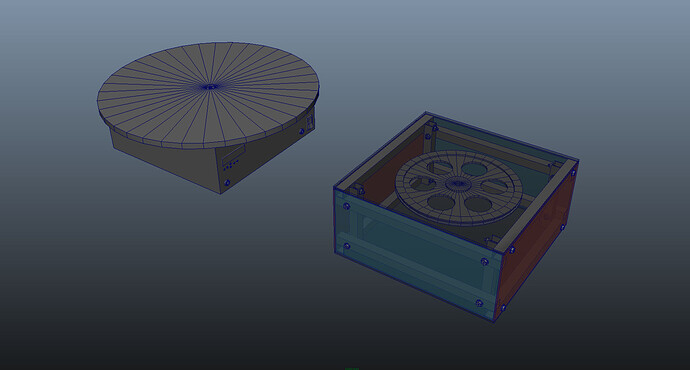
Another motorized Lazy Susan, but with some flavor. Please Help !

Hi there and thanks for your advice !

Project Outlines:

  • motorized Lazy Susan ( yes, I know, it's been done a thousand times )
  • it is for object VR photography ( rotate a product on the table while taking photos of it )
  • realistically I need it to work with loads up to 10kg on a platform that should fit a normal kitchen chair
  • the ambitious version should work with loads as large as 100kg ( a person's average weight ? )
  • I want it to be autonomous - no connection to computer required while operating
  • should have a display ( 2 lines x 16 chars should be enough ) for routine presets or custom cycles, and buttons to input these
  • for custom settings I want to be able to set number of photos or degree intervals, pauses between shots
  • I need it to trigger the camera ( just closing a circuit )
  • maybe a buzzer also for marking the progress, cycle start, cycle ending, feed back on pushing those little buttons

Why don't I want to do it manually ? Because I am a lazy ass, because 36 flashes even with my eyes closed is too much for me. And when you have 10 things to shoot is even worse. Then, something breaks your attention, and you have no idea if you shot position 13 or not. Or if all the flashes went off, because you went at it too soon, and the strobes didn't load fully. So, you see, when one does it manually, there is a thing called human error that ruins it all. Besides this, I love DIY projects.

Questions:

  1. What Arduino board should I use ?
    Can I control the stepper motor shield and the display and the camera triggering and the beeper with one Arduino board ? Do i need the Mega 2560 ?
  2. How powerful does the stepper motor needs to be ? I plan using a small timing pulley on the engine and a rather large wheel inside the "box" to drive the table on top, connected to the motor by a some belt. It will be in the range of 300mm diameter for the big wheel and 25mm on the engine cog. The external platform will be 400 to 600 mm diameter.
  3. If I need to use a motor that requires more amps than the Arduino can provide, how do I power the engine from external source ? I couldn't figure this so far. If you would like to give an answer .. this is where I am most confused.
  4. Do I really need a bread board ? Don't like those wires running in all directions. Don't pick on me on this please, excuse my ignorance.
  5. What do you recommend for a power supply ? Can I use a computer power supply ?

What I found so far:

Should I use something like this ?
http://shieldlist.org/sparkfun/powerdriver
http://shieldlist.org/robotpower/megamoto
http://www.robotshop.com/ca/productinfo.aspx?pc=RB-Ada-02&lang=en-US

I really want to use one of these:
http://www.robotshop.com/ca/dfrobot-lcd-keypad-shield-arduino-1.html
if not this fancy one:
http://www.robotshop.com/ca/4d-systems-1-5-oled-display-shield-arduino.html

So far I am working on a 3D model of the contraption (mechanical part), once I get it to the right proportions and scale I will post some scr caps.

I am not very good with programming, but I am not very worried about it, I should be able to do it.

Budget
Well, if I can do the electronic part of it for under 200$ I am happy. Obviously at this point I don't have a clear idea of what I need to do. So that could be too little, but if it is more than I need .. I am happy.

Thanks again for all the help and advice.
Much appreciated.

Bspin

The programming of the above should be simple enough, I think the mechanical interface will be the hardest part.

a motor that requires more amps than the Arduino can provide,

AKA just about every motor on the planet. I think you need stepper motors and you can get chips/shields to drive them for you as you have found, Rugged Circuits makes one to.

Do I really need a bread board ?

I doubt it.

How powerful does the stepper motor needs to be ?

I don't really know much about calculating that, moving once started will be easy as it will be on a large bearing, but your biggest problem will be inertia I think. It will take a lot of power to start and stop a 10/100kg object.

I would make the gearing ratio as large as possible, I'm thinking ~12mm drive or smaller and a driven pulley the same size as the plinth (400-600mm or whatever). In fact the driven pulley should actually be the plinth with a grove cut around the edge.

As for the display, one of the guys here has some LCD displays with menus etc.


Rob

Thanks graynomad.
I am also considering to buy a geared stepper motor. They seem to have a big ratio and I don't need speed, I need power.
For the mechanics I was thinking of using a bicycle axle, to which I will mount the platform and the pulley. There are for sure some things that need to be sorted out.

I went ahead and bought a breadboard and jumper wires and some other small staff.
It helps a lot to learn and experiment. It seemed that all I needed was to hook up some wires. But it is not that easy.

So far I got a stepper motor to spin in test mode with a Cytron shield.
http://www.robotshop.com/ca/cytron-3-40v-2a-unipolar-bipolar-stepper-motor-controller.html
I've been using a variable power adapter with a max output of 500mA.
The slightest touch on the engine shaft makes it stop, or rotate CW then CCW in an erratic behavior.
On the other hand the motor isn't suppose to suck that much power at 12V.
( Motor Specs attached )

I don't really get it how to transmit something through UART so far, what do I need to transmit ?
Pulses ? Commands ? :frowning: .. but I will figure it out eventually.

The tutorials that I've found for controlling a stepper motor using an Arduino Board require using a H bridge or a Darlington Array. Instead of that I have the Cytron thingy to which I need to send some UART stuff.

thinking of using a bicycle axle

Bicycle axles are designed to take force at right angles to the bearings, I think you need a thrust bearing or a proper lazy susan bearing. Both are designed to isolate two parallel planes which is what you are doing. Over here are least you can get the LS bearings in any hardware store, although I've never looked at one closely to see the quality.

A thrust bearing from a car would work as well.

In all cases though the platform will be much larger than the bearing so if the object is not well placed things could get a little wobbly. Once again a lazy susan bearing is better because they are very large, maybe 10 or 12". My chair is sitting on one as I type.

Are you using the motor at the centre of the turntable? If so you have no mechanical advantage but if the gearing is high maybe that's OK.

I don't really get it how to transmit something through UART so far

Serial.print (somedata);

Although if you are not using a Mega you may have to use New Soft Serial.

what do I need to transmit ?

It looks like it has a simple command set that is just ASCII characters. So for example

Serial.print ('F');

looks like it stops the motor.

The tutorials that I've found for controlling a stepper motor using an Arduino Board require using a H bridge or a Darlington Array

Are of no use to you.

I've been using a variable power adapter with a max output of 500mA.

That's 2x what the motor needs so should be OK, I don't know much about steppers though, the current spec is "per phase" do two phases every work at the same time?


Rob

Re the bearings, I think you said the load could be 100kgs before, a trailer stub axle will work well for that sort of load, same as a bicycle axle in relation to the load direction to the bearing but they are designed for 1 tonne or thereabouts and have tapered bearing so you can torque them down to remove any play.

They are cheap as well IIRC, although I haven't bought one for a few years.


Rob

I used to work on industrial CAT scanners, and they typically used metalworking lathes geared right down to rotate the workpiece.
Mounting vertically might be tricky.

Thanks for all the suggestions. It really does help.
And I have good news.
It's a breakthrough: I finally can control the stepper motor through UART.

This triggered it: Serial.print ('F');. Why didn't I see it in the manual ? It is very clear !
Thanks again Graynomad. Much appreciated.
I could have published the code I guess and that would have brought me relief sooner. Live and learn.

I've been watching and reading tutorials for hours for the last few days.
When I saw that thing posted here it triggered the final click, that could be it ! Lets try to change commands like "S" to 'S'.

Thanks Rob, will consider the options you suggested. But now the mechanics part seems light years away.
The plan was to have a high gear ratio between the motor axle / cog and a large pulley inside the "box" - housing of the whole contraption. Yes indeed, 500 mA should be more than enough for now at least.

This is obviously a much larger project than I though it will be. My deadline ( before the end of the year ) it's probably not that realistic.
I should have broken everything up into smaller pieces software / serial connection / LCD / buttons / monitor data / hardware / mechanics. I didn't see it.

Link to Cytron 3-40V, 2A Unipolar / Bipolar Stepper Motor Controller MANUAL
http://www.robotshop.com/ca/content/PDF/users-manual-sd02b.pdf
See page 31 for codes.

I got into some other problems, before making this little progress.
(1)
The LED on pin 13 on my Mega it's very faint now.
An attached LED on the same D13 is just as faint.
Blinks to LED on D13 are again very faint. It reads a constant 1.73V on a voltmeter.
Reset seems to work fine but it's no longer that clear that there was a reset.
This happened while trying to send from D13 signals to Pulse on Cytron, the alternative method to stimulate the controller.

(2)
When I got the thing going, I had only Tx (on Mega) to Rx (on Cytron Motor Shield) hooked. Is this normal ?
Don't you need the Rx - Tx conected ? What about the GND on the Cytron Shield ? GND wasn't connected either. What do I hook that to on the Mega ? I used separate power sources for the Mega (USB) and Cytron (PSU)

(3)
Previously while attempting to do this, as soon as I had Tx(Mega) conected to Rx(Cytron) the Tx led will start blinking at a very high frequency. That seems strange to me. Yes I was sending stuff, but not at that rate. But what do I know. I will feel to ashamed to publish that piece of code.

(4)
There seemed to be current leaks from one board to another .. the power LED on Cytron will come up when there was no current on the that board, while connecting Rx and Tx wires from Mega.

(5)
Uploading gets stuck, many times. Upload button stays highlighted to no resolve.
(6)
Serial Monitor won't show.
(7)
"COM in use" message.
(eight)
Lots of frustration.

This is a variant of the code I had success with: ( I can't make it run at this time anymore )

int incomingByte = 0;	// for incoming serial data
int LEDpin = 12;        // define which pin to use for the LED

void setup()
{
  pinMode(LEDpin, OUTPUT);

  Serial.begin(9600);

  Serial.print('U'); // set boud rate of controller
  Serial.print('1'); // to 9600
}

void loop()
{
  // blink routine to mark the start into the progress of the sketch
  digitalWrite(LEDpin, HIGH);   
  delay(100);               
  digitalWrite(LEDpin, LOW);    
  delay(100);                

  Serial.print('O');  //turn on stepper motor
  delay(1000);               

  Serial.print('G');  // Run the stepper motor
  delay(1000);

  Serial.print('<');  //rotate clockwise
 
  Serial.print('S');  //set speed
 
  Serial.print('9');  // speed to 9 out of 255
  delay(1000);

  Serial.print('F');  //brake stepper motor
  delay(3000);

  Serial.print('G');  //run the stepper motor
  delay(2000);

  Serial.print('C');  // Request Current Status
  delay(1000);

  if (Serial.available() > 0)
  {
  incomingByte = Serial.read();  // read the incoming byte:
  Serial.print("I received: ");
  Serial.println(incomingByte, DEC);  // say what you got:
  }

}

I have less then 5h of sleep left for tonight. Should be enough. I will be dreaming of neatly running stepper motors.
Sorry for the long post. Tying to be as explicit as possible. I also feel kind of stupid.
Thanks!

(1) ? Maybe you've stuffed the pin.

(2) If you are only sending commands there's no need for the other half of the serial link. However if you read data back from the controller (I didn't read the data sheet that well) you do.

Now I see

Serial.print('C');  // Request Current Status

so yes you need to connect the other Rx/Tx pair.

What about the GND on the Cytron Shield ?

GND must be connected between all involved circuits.

(3) ?

(4) It's quite common for a modern chip to be powered through an IO pin because of the ESD protection diodes. So your Arduino Tx is probably providing power to the Cytron processor through its Rx pin.

(5)(6)(7) You seem to be using Serial, this is connected to the USB interface chip so it is usually not recommended to also use it for your application. If you are using a Mega swap to another UART.

My deadline ( before the end of the year ) it's probably not that realistic.

Oh I don't know, you've got about 14 months, or do you mean this year?

There might be a problem with this code

Serial.print('C');  // Request Current Status
  delay(1000);

  if (Serial.available() > 0)
  {
  incomingByte = Serial.read();  // read the incoming byte:
  Serial.print("I received: ");
  Serial.println(incomingByte, DEC);  // say what you got:
  }

If the Cytron returns more that one byte. You only read one then send the 'C' command again. If it only responds with a single byte you're OK.


Rob

I have the 6" lazy susan bearings rated to take 500 lb load, that's over 200 Kg.

Here's the 12" which the wider the circle the more stable and easy to turn your even wider load will be:

These beat H out of trying to mess with much heavier or otherwise unsuited stuff. If you put your load on top then a -small- wheel out at the edge in contact with the table top or floor the rig is sitting on will be able to turn the whole thing in a very slow and controlled manner without using enormous power or needing much in the way of transmission.

Think of a small kid pushing a playground merry-go-round massing many times what the kid does.
http://www.google.com/imgres?imgurl=http://image.shutterstock.com/display_pic_with_logo/153391/153391,1212514930,5/stock-photo-a-playground-merry-go-round-in-the-grass-13344022.jpg&imgrefurl=http://www.shutterstock.com/pic-13344022/stock-photo-a-playground-merry-go-round-in-the-grass.html&h=322&w=450&sz=81&tbnid=1A74Gd779g0F4M:&tbnh=90&tbnw=126&zoom=1&docid=GoiXUd8LHBNPwM&hl=en&sa=X&ei=DymoTrqBAoHg0QHMnaC7Dg&sqi=2&ved=0CGcQ9QEwBA&dur=8000

You still need at least one motor driver. If you need it to be able to stop quickly then work on brakes that make direct contact with the surface below the unit (like feet stuck down and dragging to stop the merry-go-round/carousel) and leave the poor drive motor and wheel out of it!

Another thing to illustrate is go find a heavy motorized potter's wheel and look at that. There is the wheel on top and shaft below to another wheel at the base. The potter may kick the base wheel around or press a foot switch that brings an electric motor with small wheel turning on the shaft down against the outside rim of the big base wheel. 1/4 horse motor turns the concrete-filled steel wheel nicely. You won't need anything like that much power!

A small diameter wheel turning against the rim of a large diameter wheel has great mechanical advantage. Wheels are levers after all, a 50-lb kid can lift a car with a long enough lever. Just not quickly!

The complicated parts are more likely what the load on top is doing and how it knows where it's pointing.

I could be wrong but I think a "pottery whirler" would be ideal for your application - do a search for them.
They will usually rotate on a stainless steel bearing or ball race, all you would need to do would be attach your pulley to the shaft.
The top will normally have concentric circles etched on them allowing you to position your object centrally easily.

I agree with Graynomad that inertia is important to consider. Although you say you are in no hurry I think you will find that you want to accelerate and decelerate the mass as it moves between positions. It sounds like you just want to take a picture every 10degrees of rotation so it should be possible to get develop a simple accelerate, cruise, decelerate algorithm by experiment.

Thank you all.
Quick notes.
I will search the pottery whirler. Sounds like a very sturdy application with a very similar functionality.
I did have in mind short acceleration, and deceleration rather than a linear move.
Hope I don't have to install a break. I will keep my loads small, and if I really need huge loads I guess I will implement that too. Maybe with a solenoid with a breaking pad. What a circus it will be !
I did consider Lazy Susan barrings too.
Please have a look at the 3 images attached for really WIP, basic mechanical plan.
Right now I am trying hard to get the software going.
Other than that 10 second fluke when it worked I hadn't had anymore luck. I was so excited .. I didn't save the sketch, I don't remember pretty much anything about what I had going. Pretty silly of me.

Progress:
I get the COM busy and stall while trying to load sketches WHEN the Cytron Controler is POWERED ON and CONNECTED to the Arduino Mega.
If if disconnect the shield things load properly.

You seem to be using Serial, this is connected to the USB interface chip so it is usually not recommended to also use it for your application. If you are using a Mega swap to another UART.

Do you mean swap to another RxTx pair ? ie should use Serial1 ?
Should I have another intermediary device between Cytron UART and Mega ?
Does it mean that I need to create another COM port and use that somehow ?
I understand that COM X is used for communication between Mega and computer. Do I need to assign a COM to the UART ?
I am a bit confused about how data travels. What gets from where to where.
I am using the COM X when I upload. Am I using COM X when I send to UART as well ?

Thanks.
Have a look at the Scr shots for mechanical WIP sketches but again, mechanical part seems to be light years away.
This project sure keeps my mind busy. I wont give up.

Do you mean swap to another RxTx pair ? ie should use Serial1 ?

Yep.

Should I have another intermediary device between Cytron UART and Mega ?

Nope.

Does it mean that I need to create another COM port and use that somehow ?

Nope.

I am a bit confused about how data travels. What gets from where to where.

The Mega has 4 UARTS, called Serial and Serial1/2/3. Serial is used to talk to the PC and for sketch downloads. It is hardwired to the USB interface chip which is why it's not recommended that you also try to use it for something else.

So change all the code that talks to the Cytron to use say Serial1 and move the wires. That should fix all the uploading and related problems.

I get the COM busy and stall while trying to load sketches WHEN the Cytron Controler is POWERED ON and CONNECTED to the Arduino Mega.

Because when it's connected to Serial it's interfering with the Mega's other serial functions like uploading.

If if disconnect the shield things load properly.

Because when it's connected to Serial it's interfering with the Mega's other serial functions like uploading. :slight_smile:

Pic #3 is the same as #1.


Rob

Thanks Rob, did try that (new RxTx pair), will try it again.
...
Seems to be working. At least something is happening. See attached pic.

There are two problems that I have
(1)
How will I get some feed back ? (no blinking little LEDs suggesting that something is going on)
(2)
Why is it that I don't see anything going on in the Serial Monitor while using Serial1 ?

And one more question if you please:
(3)
How will I be able to set speed to 100 ? How do I send 100 ? Does it understand 100 ? or do I need to send 1 and then 0 and another 0 ? See attached pic form Manual.

The current code that I am using:

int LEDpin = 12;        // define which pin to use for the LED

void setup()
{
  pinMode(LEDpin, OUTPUT);

  Serial.begin(9600);

  Serial.println('U'); // set boud rate of controller
  Serial.println('1'); // to 9600
}

void loop()
{
  // bmark start of the sketch
  digitalWrite(LEDpin, HIGH);   
  delay(100);               
  digitalWrite(LEDpin, LOW);    
  delay(100);                

  Serial.begin(9600);
  Serial1.begin(9600);
  Serial2.begin(9600);
  Serial3.begin(9600);
  delay(1000);

  Serial.println('O');  //turn on stepper motor
  delay(1000);
  
  Serial.println('S');  //set speed
  Serial.println('100');  // speed to X out of 255
  Serial.println('<');  //rotate clockwise
  delay(1000);

  Serial.println('G');  // Run the stepper motor
  delay(1000);

  Serial.println('F');  //brake stepper motor
  delay(3000);

  Serial.println('G');  //run the stepper motor
  delay(2000);

 // mark start of flush and end - some clean up
  digitalWrite(LEDpin, HIGH);   
  delay(200);               
  digitalWrite(LEDpin, LOW);    

  Serial.flush();
  Serial1.flush();
  Serial2.flush();
  Serial3.flush();

  Serial.end();
  Serial1.end(); 
  Serial2.end();
  Serial3.end();

// mark end of serial com, wait 3s before starting all over  
  digitalWrite(LEDpin, HIGH);   
  delay(500);               
  digitalWrite(LEDpin, LOW); 
  delay(3000);

}

This is what I am trying to run now.
The LEDs on the Cytron show that it gets stuck on a certain pattern 0110, and sometimes this pattern changes to something else.

(4) Sorry, one more Q
Once I send one command to run ... do I need to keep sending it ? In a loop ? Like GGGGGGG (Run stepper motor ).
Will give it a try anyway.

The missing pic also was attached. The motor will be in one of the corners.

Many thanks to my mentors.

How will I get some feed back ? (no blinking little LEDs suggesting that something is going on)

Do you mean from the Cytron?

Why is it that I don't see anything going on in the Serial Monitor while using Serial1 ?

Hint, it's not called "Serial1 monitor". As I said before, Serial talks to the PC, if you want to see something on the PC you have to use Serial not Serial1.

How will I be able to set speed to 100 ? How do I send 100 ? Does it understand 100 ?

It looks like it wants an ASCII 'S' followed by a binary speed. So I think

Serial1.print ('S');
Serial1.print (100);

will do it.

You are still using Serial for the Cytron, use Serial1.

As it stands I don't see how the Cytron is doing anything because you never send it any data. OTOH you should be seeing all sorts of crap on the serial monitor.

Never use println() for the Cytron, only print(). println() appends a CR/LF which will confuse the Cytron.

The LEDs on the Cytron show that it gets stuck on a certain pattern 0110, and sometimes this pattern changes to something else.

Given that you aren't actually sending anything to the Cytron on Serial1 that must be totally random because you don't have the GNDs connected. You must connect the GNDs.

No need to flush() the serial ports.

Move all the Serial.begins() into the setup() func.

Get rid of all the Serial.ends().

Change

Serial.println('1'); // to 9600

to

Serial.print(1); // to 9600

Once I send one command to run ... do I need to keep sending it ? In a loop ? Like GGGGGGG (Run stepper motor ).

No, if that was the case there'd be no point in the S command.

Try all that then re post the code.


Rob

You should look at a set of the Lazy Susan bearings because they are 4x stronger than you need, work very well and cost less than $15. They are also quite thin, less than 2cm thick, and do not have any axle so the load is spread wide over many ball bearings which is why the LS has such high weight capacity yet weighs very little.

You go with a pottery wheel and you add the considerable weight of the pottery wheel to what your motor and brakes must handle. Pottery wheel is made heavy to keep turning constant while the potter shapes the clay above. I have 9 credits in ceramics most of my art electives, I know the wheel quite well. A good one is heavier than the potter using it.

The Lazy Susan bearings are functionally two square plates with bearings between and a big hole through the center. The plates have small holes at the corners to mount with. Bolt or screw a base plate to the bottom and your project on top. You can hide drive and brakes inside that if you need. Just a small motor with small wheel on the shaft mounted to the upper part with wheel edge in contact with the base plate below. But the smart thing would be to drive out at the edge.

And here is a question. Do you need to turn the whole mass or just a camera? Does it need to turn around and around or will one 360 or less turn do? You may want to do like R2D2 and only turn the top.

Hope I don't have to install a break. I will keep my loads small, and if I really need huge loads I guess I will implement that too. Maybe with a solenoid with a breaking pad. What a circus it will be !

If you are using a stepper motor for this you definitely should not need a brake. If you do you have done something wrong either you are just accelerating/decelerating too hard, or your gearing is wrong or the motor is underpowered.

I took a break from the stepper business for a couple of days to play with the display screen I got. That proved to be less frustrating than the stepper. Made some progress there at least. Still a long way to go.

So tonight I've tried again and this is my last attempt, and I am going to either return or have components replaced as defective, because I can't find any way to make them run.

What am I playing with:
Arduino Mega + Cytron SD02B + 3 different types of unipolar stepper motors + USB to UART converter Cytron UC00A

I am trying to control a stepper motor through UART as described in the controller's manual.

http://www.robotshop.com/ca/cytron-3-40v-2a-unipolar-bipolar-stepper-motor-controller.html
http://www.robotshop.com/ca/rbsoy03-soyo-unipolar-stepper-motor.html
http://www.robotshop.com/ca/productinfo.aspx?pc=RB-Cyt-43&lang=en-US

With two motors (5wire, 7.5 step) all I got was random vibration even on test(button) on motor shield.
With last bought motor Soyo (6wire, 1.8step) performs as expected on test(button) on motor shield.

No program I've tried gave any constant and anything more than random rotation, not a random succession of functions ( turn left / right / stop in some random combination) just pure random vibration.

With Soyo motor I didn't get anything at all, except proper behavior while testing, as mentioned above.

This is the last piece of code I've tried.

void setup()
{
  Serial1.begin(9600);
  Serial1.print('U');  //set motor controloer boud rate to
  Serial1.print(1);    // 9600bps ( same as the reset button on SD02B )
}

void loop()
{
  Serial1.print('O');  //turn on stepper motor
  delay(1000);
  Serial1.print('S');  //set speed
  Serial1.print(9);    // to XX
  Serial1.print('<');  // rotate counterclockwise
  
  Serial1.print('G');  // run the stepper motor
  delay(2000);
  
  Serial1.print('F');  //brake stepper motor
  delay(2000);
}

I've striped it down to anything that would supposedly show me something. Anything.
I've attached a photo of my contraption. Schematic should be pretty obvious.

I've bought the Cytron UC00A adapter (USB to UART) and try to do what I didn't seem to be capable to do with Mega. The adapter seems to be defective. It is not detected in Win7 at all, and I noticed a small component getting really hot, at which point I simply unplug it. See attached pic for details.

So ? Please, any suggestions ?
Thanks !

So you got the motors and ran tests on each one just with power and control hooked up and couldn't even get the shafts to turn properly with no loads?

Yes, that sums it up ! No luck.
And getting that USB to UART converter defective right from the bag was another blow.
I've spent so many hours trying to get that shield to work.
RMA time.

As an aside from the stepper motor drive issues, how fast do you plan to rotate this turntable, how accurately do you need to have it positioned when you take the picture, is the angular change between pictures going to be fixed or programable, and how important is it that the object is stationary when you take the picture? If you have a reasonably fast shutter and a slow moving object you may not need to stop it at all. That would simplify things enormously, I would think. (Starting or stopping the turntable abruptly is probably a very bad idea because you're liable to dislodge the object you're trying to photograph. If you need to stop it, that implies ramping the speed up and down in a controlled way and that implies some pretty accurate position feedback.)

How high off the ground do you want the turntable surface to be? I imagine you'd like to have it at a convenient work height. If you can arrange to use some standard domestic item such as an office chair as the base for your turntable, I think you'll find that much easier and cheaper to make reliable. And you could get casters and so on for free.