Agreed 100%. I was just about to suggest the same thing but you beat me to it.
I still find small signal BJT's useful in various situations. But for something like the OPs application above, modern logic level mosfets are so just far ahead.
If you want variable speed for the motor you could use a PWM output from the arduino, but in that case the diode should be a fast one eg a UF4002. The 1N400x series are slow recovery and could overheat.
I have found that unless the right words are used, the thinking often remains muddled. It might sound pedantic if you don't fully appreciate the difference but you would never use this phrase if you had a good handle on things.
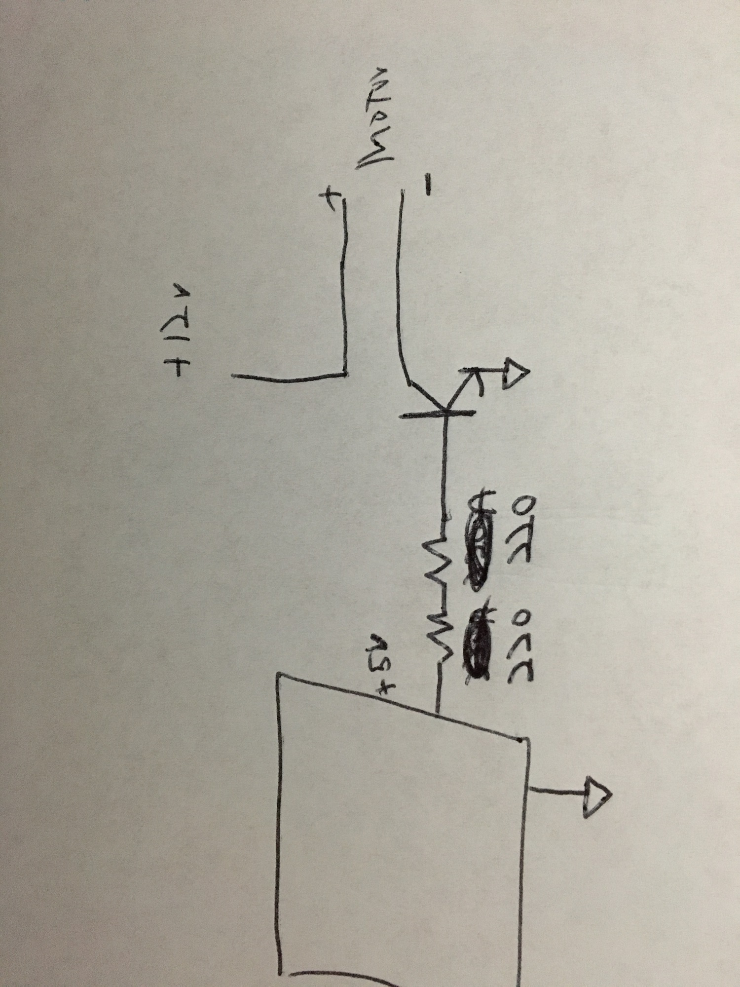
I am up for using what ever the best overall solution is be its the IRL1104 or something else. I will look into that one. I will try to get a picture going of what i have read to make sure i am processing it correctly.
The graph of a TIP120 shows a 0.75volt loss at 400mA motor current (with 1k base resistor).
I don't think that will be a problem with 12volt available (11.25volt left for the motor).
It will dissipate 0.3watt at that current (warm, but not hot).
A mosfet will only be a fraction better (in this case).
Leo..
robkiller:
I am up for using what ever the best overall solution is be its the IRL1104 or something else. I will look into that one. I will try to get a picture going of what i have read to make sure i am processing it correctly.
Yeah show what you've attempted so far, because the TIP120 should definitely work.
The thing about logic level mosfets is just that they are faster, more efficient and easier to drive (than BJTs). If for example you were trying to switch higher currents, or if you wanted to apply rapid PWM to the motor, then the mosfet could have significant advantages.
Having said that however, for simply static switching the motor on and off the TIP120 will still work just fine. So we need to see your original circuit to see what went wrong, otherwise you will just make the same mistake with the mosfet.
The diode (e.g. 1N4004) goes across the motor.
Cathode (ring) to +12volt, and anode to the collector.
The diode kills back-emf from a motor/solenoid when the transistor turns off.
The spike (without diode) could be hundreds of volts and could kill the transistor.
I assume you have connected 12volt negative to the emitter.
And Arduino ground also to the emitter.
Leo..