I have an ESP32 board i want to switch relays with.
I have connected a 3.3 to 5V logic level converter between GPIO and relay. When I measure with a multimeter, I get 5V when GPIO is switched on.
However when a relay (HF41F) is connected to it, the voltage drops to about 2.5V and relay does not trigger. 5V power supply is 2.4A, so it should be plenty. The relay triggers if I connect 5V to it directly, so it should be functional.
Is the logic level converter too cheap or am I doing something wrong?
Always show us a good schematic of your proposed circuit.
Show us good images of your ‘actual’ wiring.
Give links to components.
In the Arduino IDE, use CtrlT or CMDT to format your code then copy the complete sketch.
Use the < CODE / > icon from the ‘posting menu’ to attach the copied sketch.
I wonder, the relay which is inductive will require over 30 mills at 5V. The Arduino is not rated for that much current. This may help you understand what is happening and consider yourself very lucky if the ESP has not been damaged. Gil's Crispy Critter Rules for Processor Hardware:
Rule #1: An Arduino is NOT a Power Supply!
Rule #2: Never connect anything inductive (motors, speakers) directly to an Arduino!
Rule #3: Avoid connecting or disconnecting wires while the power is on.
Rule #4: Do not apply power to any pin unless you are certain of what you're doing.
Rule #5: Do not exceed the maximum voltage ratings.
Rule #6: Many Arduinos cannot power transmitters directly.
Rule #7: Before powering your project, take a break and double-check the wiring.
LaryD’s Corollaries:
Coro #1: When starting out, add a 220Ω resistor in series with both input and output pins to protect against shorts.
Coro #2: Invest in a Digital Multi-Meter (DMM) to measure voltages, currents, and resistance.
Note: Violating these rules can turn your Arduinos into crispy critters. For optimal performance, keep your wires under 25 cm (10 inches).
Can you please post a copy of your circuit, a picture of a hand drawn circuit in jpg, png?
Hand drawn and photographed is perfectly acceptable.
Please include ALL hardware, power supplies, component names and pin labels.
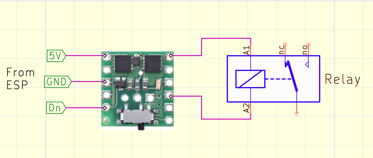
Are you powering the DC-DC converter from the GPIO?
If so STOP, the output current from your ESP is not enough to power a 5V DC-DC converter.
DC-DC converter gets 5v power directly from the same PSU that powers everything (2.4A). Its 3.3v is connected to ESP 3.3v
I will try to draw it, it is currently in my mind only
It is quite hard for me as I am more of a software/network person, but I try to learn. While I draw, enjoy this mess:
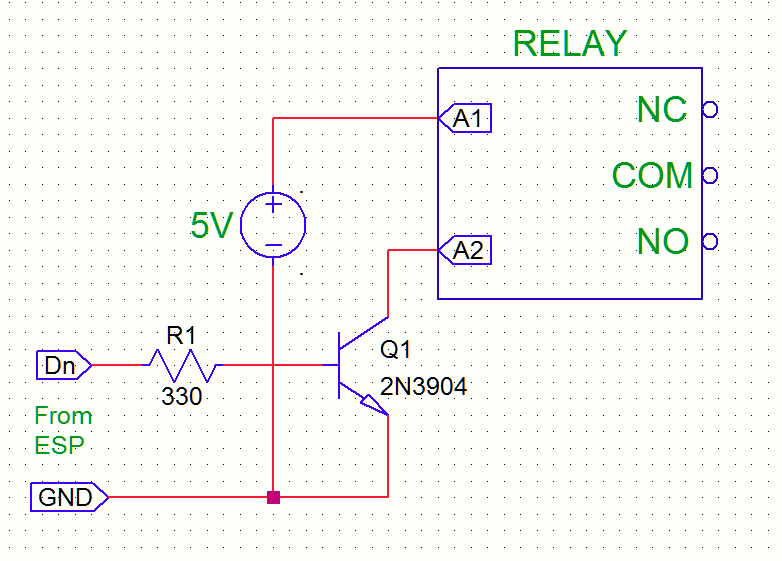
As indicated previously the logic level shifter are not for powering relay coil, and the wiring of coil is wrong, be careful with such wiring errors, the microcontroller is at high risk of being damaged. Using a switching transistor MOSFET well enslaved is a good solution for this type of setup, the use of an optocoupler could also do the trick very well to order this relay.
ESP 3.3V is fine. At the most each will only draw 1uA (microamp) when idle and only draw 1.5mA when you ask for a temperature. So 20 more would be no problem but remenber there should only be one pullup resistor on the bus.