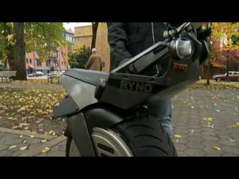
Hello
This is my first post, I have been lurking on this site as a guest for a while, and wanted some insight on how exactly to go about this process.
I would like to replicate this brushless unicycle.
I have been inspired by this project to build a DiY version, and would greatly appreciate the help along the way. I have some of the parts for this project, namely,
- brushless motor
- ebike controller
- arduino mega
seeking to buy 3-axis of freedom gyroscope
I am struggling to figure out how to control the 0-5k resistor throttle using the arduino
or
variating the 0-5v hall effect sensor, and mimicking the output accordingly
I put my meter in current mode and the the current is 0.5mA, which makes sense if there's an internal 10kohm pull up resistor to 5v.
I dug out an old 5kohm pot and put it across the controller end of the cable. With the pot across red and yellow, with the wiper on blue, the motor runs fine, and the voltage sense is still backwards. High voltage is stopped, low voltage runs fast. The odd thing is that there's only a 0.5 volt range from stop to full speed; and it's offset, too. Specifically, 3.0 volts is full speed, and 3.5 volts is full stop. Very narrow range. This is with the wheel off the ground though -- maybe it has a wider voltage swing under load.
There is a reverse on the controller, that I have hard-wired, adding a fourth wire to the 3-wire throttle. (one is +, other is -, and one is neutral)
so four cables
Could this be interfaced similarly to a stepper motor?
Is it more similar to running a servo motor?
I've concluded that, shorting the the sense wire input to gnd runs the motor at full forward speed, shorting the reverse runs the motor at 40% power.
Please let me know of any tips to interface a brushless motor controller to an arduino
many thanks
Dean
