Arduino and Sensor (Humidity, CO2 and Temp) of RS485

Hello Everybody, I am having problems in getting data, i.e temperature, humidity and CO2 from the sensor by RS485 protocol. I have read about the relevant topic, especially getting data from NPK sensor.
I use Mega2560, MAX485 module and the sensor.
RS485Module


This is the sketch used.
CO2TempHum.ino (5.1 KB)
This are the results I get:
a. 5 second delay
Delay5Sec
and this 3 sec delay
Delay3Sec
It seems that it does not perform to the expectation, only after about 10 loops it give a reasonable readings and after that it start to give error. It seems that number of loops will give the readings and not the time delay. I also used altsoftserial.h but with errors. I also tried using USB-RS485 dongle,
USB
and it give instant and reasonable reading. The reading are as shown above. Apart from the software supplied by the producer, I also use CoolTerm and it performs. These are data obtained.

and
Humid
.I was wondering why one method succeed and the other failed. Any suggestion how to get the data by using Mega and RS485 module?

/*Materials :
 1* Arduino Mega
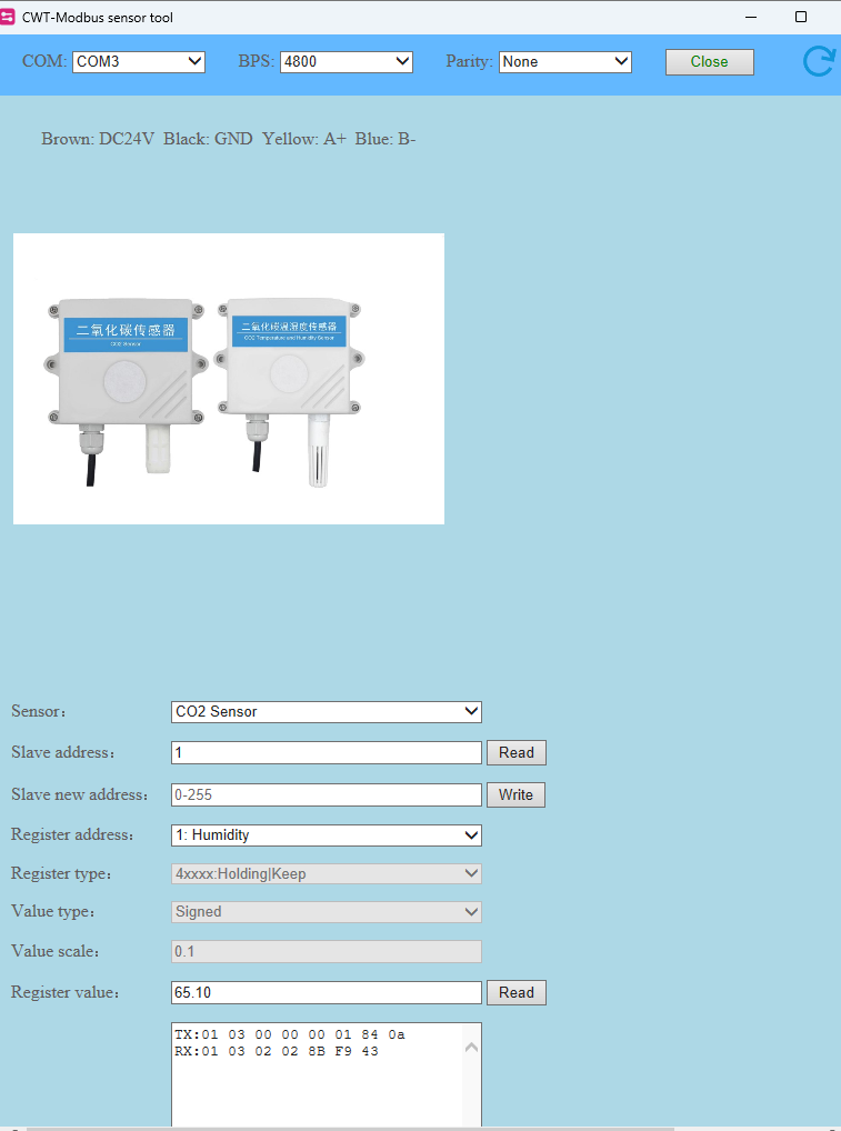
 1* CWT CO2 - RS485 MODBUS protocol of communication
 1* MAX485 Module

*/

//#include <SoftwareSerial.h>/ https://github.com/PaulStoffregen/SoftwareSerial
#include <SoftwareSerial.h>

//#define RX 10       //Serial Receive pin
//#define TX 11       //Serial Transmit pin
//#define RTS_pin 12  //RS485 Direction control
//#define RS485Transmit HIGH
//#define RS485Receive LOW
#define RE 8
#define DE 7

//SoftwareSerial RS485Serial(RX, TX);
const byte CWTH2O_request[] = { 0x01, 0x03, 0x00, 0x00, 0x00, 0x01, 0x84, 0x0A };   // inquiry frame
//const byte CWTTemp_request[] = { 0x01, 0x03, 0x00, 0x01, 0x00, 0x01, 0xd5, 0xca };  // inquiry frame
//const byte CWTCO2_request[] = { 0x01, 0x03, 0x00, 0x02, 0x00, 0x01, 0x25, 0xca };   // inquiry frame
const byte CWTALL_request[] = { 0x01, 0x03, 0x00, 0x00, 0x00, 0x03, 0x05, 0xCB };   // inquiry frame
//byte values[10];
byte CWTH2O_buf[8];
//byte CWTALL_buf[11];

void setup() {

  //pinMode(RTS_pin, OUTPUT);
  pinMode(RE, OUTPUT);
  pinMode(DE, OUTPUT);

  // Start the built-in serial port, for Serial Monitor
  Serial.begin(9600);
  Serial.print("Delay 3 Sec & CWTH2O");
  Serial.println();
  // Start the Modbus serial Port, for anemometer
  //RS485Serial.begin(4800);
  Serial1.begin(4800);
  delay(1000);
}

void loop() {

  //digitalWrite(RTS_pin, RS485Transmit);     // init Transmit

  //RS485Serial.flush();
  digitalWrite(DE, HIGH);
  digitalWrite(RE, HIGH);
  delay(10);
  //Serial1.write(CWTALL_request, sizeof(CWTALL_request)); 
  Serial1.write(CWTH2O_request, sizeof(CWTH2O_request)); 
  //RS485Serial.write(CWTH2O_request, sizeof(CWTH2O_request));
  //RS485Serial.flush();
  Serial1.flush();
  digitalWrite(DE, LOW);
  digitalWrite(RE, LOW);
  //delay(2);
  //digitalWrite(RTS_pin, RS485Receive);      // Init Receive
  Serial1.readBytes(CWTH2O_buf, 8);
  //Serial1.readBytes(CWTALL_buf, 11);
  //Serial.print("Humidity: ");
  for (byte i = 0; i < 7; i++) 
  {
    //values[i] = Serial1.read();
    Serial.print(CWTH2O_buf[i], HEX);
    //Serial.print(values[i],HEX);   
    Serial.print(" ");
    delay(100);
  }
  Serial.println();
  delay(3000);  
}
 // RS485Serial.readBytes(CWTH2O_buf, 8);


The correct sketch. (sorry for the clumsiness)

the Mega has hardware serial ports so use them rather than software serial emulations, e.g. Serial1 is on pin 18 TX1 and 19 RX1
this is a RS485 test program I use on the Mega which uses Serial1

// RS485 using arduino mega Seial1 pins 18 and 19 - also works on the arduino DUE

#define RS485Serial Serial1  // hardware serial port on Mega

// connect RS485 DI and RO to Mega Serial1
//  Mega Serial Receive  pin 19 to RO
//  Mega Serial Transmit pin 18 to DI
// RS485 DE and RE to Mega pins 2 and 3
#define DE 2  //RS485 Direction control pin
#define RE 3  //RS485 Direction control pin

// RS485 VCC Mega to 5V Due to 3.3V

#define RS485Transmit HIGH
#define RS485Receive LOW

#define Pin13LED 13

void setup() 
{
  while (!Serial)   ;
  delay(1000);
  // Start the built-in serial port, probably to Serial Monitor
  Serial.begin(115200);
  Serial.println("Use Serial Monitor, type in upper window, ENTER");
  pinMode(Pin13LED, OUTPUT);
  pinMode(DE, OUTPUT);
  pinMode(RE, OUTPUT);
  digitalWrite(DE, RS485Receive);  // Disable RS485 Transmit
  digitalWrite(RE, RS485Receive);  // Disable RS485 Transmit
  RS485Serial.begin(115200);       // set the RS485 data rate
}

// loop sending data from Mega to RS485 and receiving data
void loop() {
  digitalWrite(Pin13LED, HIGH);  // Show activity
  if (Serial.available()) {            // Arduino Serial data avaliable?
    digitalWrite(DE, RS485Transmit);   // Enable RS485 Transmit
    digitalWrite(RE, RS485Transmit);   // Enable RS485 Transmit
    RS485Serial.write(Serial.read());  // Send byte to Remote Arduino
    digitalWrite(Pin13LED, LOW);       // Show activity
    RS485Serial.flush();               // wait for byte to be transmitted
    digitalWrite(DE, RS485Receive);    // Disable RS485 Transmit
    digitalWrite(RE, RS485Receive);    // Disable RS485 Transmit
  }

  if (RS485Serial.available())  // RS485 serial data available?
  {
    digitalWrite(Pin13LED, HIGH);      // Show activity
    Serial.write(RS485Serial.read());  // read character and display it
    digitalWrite(Pin13LED, LOW);       // Show activity
  }
}

note the statement

    RS485Serial.flush();               // wait for byte to be transmitted

before the transmitter is disabled - Serial.flush() checks that all the bits of the last character have been transmitted

you can use the USB-RS485 dongle to check that Mega-RS485 simple character communication is working before attempting the modbus connection

Thank you. I used Serial1. The other pins have been commented (\. It was used as a trial).

make sure you call

 RS485Serial.flush();  

after transmitting all your data and before switching from RS485 transmit to receive mode
the software serial emulators do not require it as the write methods return when the last bit transmission is complete

Yes. I call Serial1.flush();
Please see the second sketch which was post as reply. From your sketch, you use digitalWrite(Pin13LED, HIGH) and digitalWrite(Pin13LED, LOW) to show activity. For me, I just rely on the lights of TX and RX of the CoolTerm. For your information, when using CoolTerm and USB Dongle, both lights blinked (as in the picture) when I clicked the send button ( to send the inquiring frame) but when using CoolTerm and MAX485 module, only light of RX blinked.

This topic was automatically closed 180 days after the last reply. New replies are no longer allowed.